| Fields vs piezoelectricity |
9 September 2020
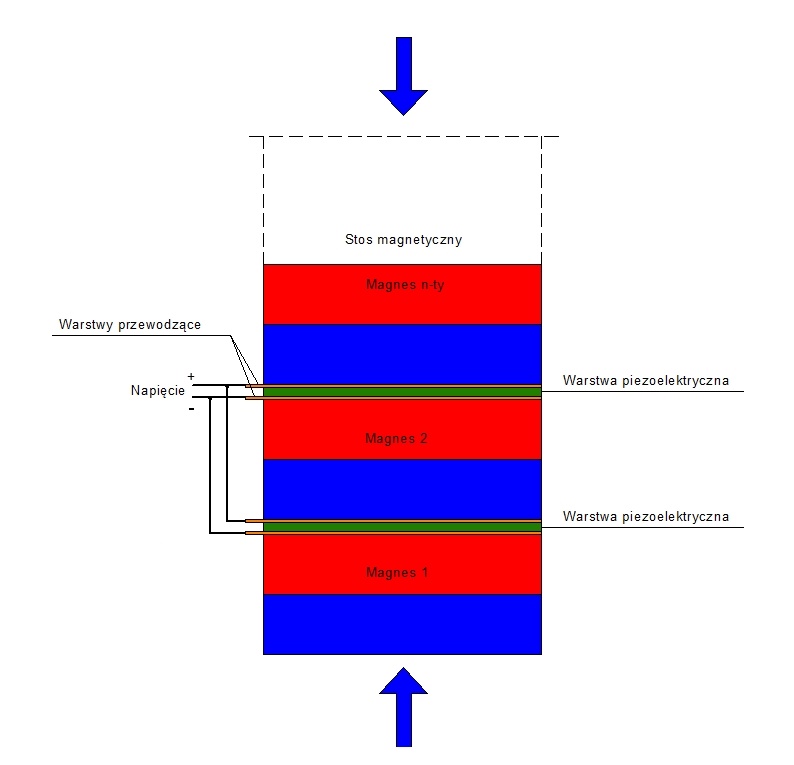
Magnetic and gravitational fields, along with piezoelectricity, may be used to create simple electricity generators (based on the principles shown in the graphics). However, to be honest, I haven't encountered similar solutions; perhaps someone has already tested them. However, for me, until such devices are verified in terms of their substance and functionality, their idea remains true, in accordance with the logic and its principles that truth remains true until proven false. Piezoelectricity, which, as we know, can generate high currents in spark gaps in cigarette lighters and igniters, is a potential source of clean energy. For example, recently there were proposals to install piezoelectric mats on highways and generate electricity from vehicles driving on them, or to harness the energy of rain falling on windows equipped with piezoelectric solar cells. How much energy there is in the environment, when we think about various natural processes, cannot be calculated in any way, but it is certainly a monstrous amount of gigawatts, wasted and dissipated with the passage of time and weather and environmental variability, which could be harnessed to work for the good of the economy and to power, for example, homes.
| Gravitational field vs piezoelectricity |
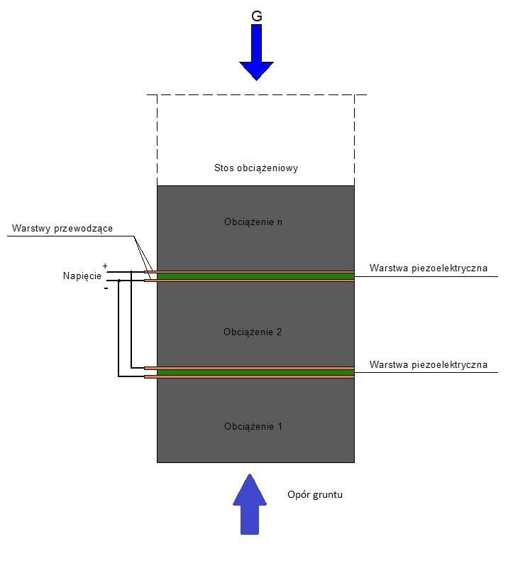
| Electromagnet and piezzoelectric effect |
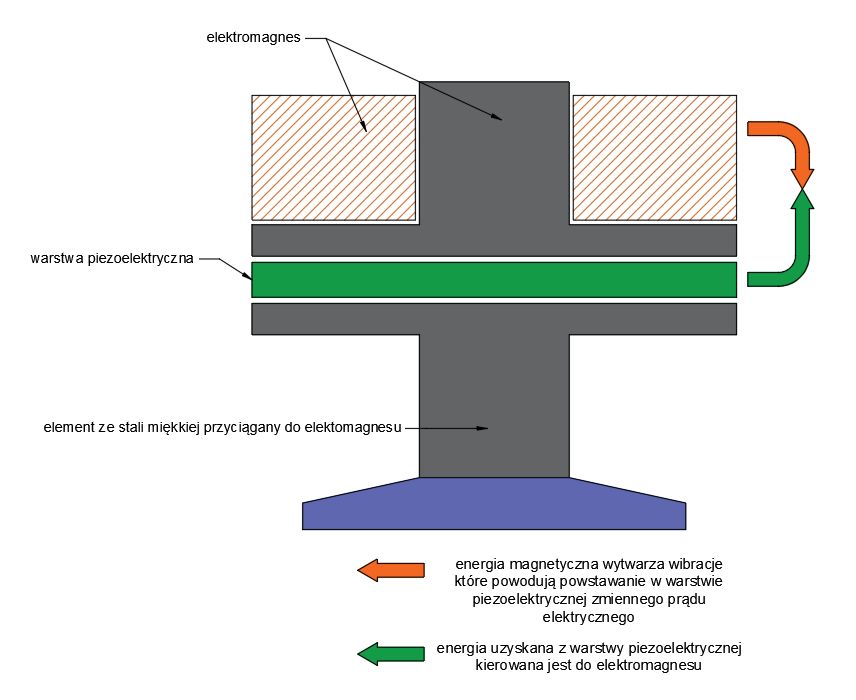
| Magnetic field vs piezoelectricity |
9 September 2020
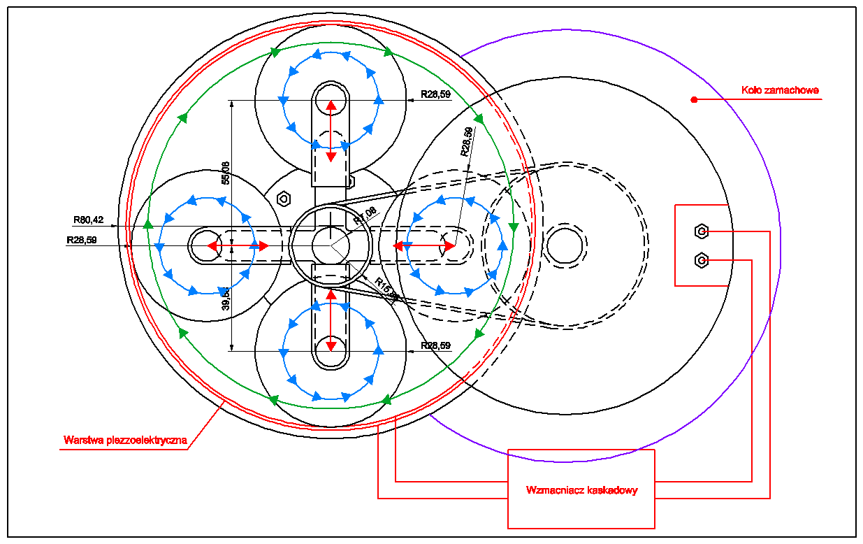
Below is a piezoelectric and inertial system for generating electrical energy and inertial drive. The operating principle is simple and involves generating additional current from the variable pressure of heavy steel rollers on a layer of piezoelectric generators. These rollers are heavy, so they should easily generate energy from these generators based on the principle of time-varying pressure. These rollers rotate within the housing, along the edges from the center, where the generators are mounted. These are small, so their stroke is not excessive. Each rotation of the rollers generates sparks from the piezoelectric generators. These sparks, after being converted by the electronic system, are fed to the electric motor, which then turns the roller system. The piezoelectric generator system could also be replaced with short-stroke electromagnetic generators equipped with high-force return springs and permanent magnet coils. Each time the roller is pressed or the roller hits such a generator, the neodymium magnetic core or copper wire coil would move slightly outward toward the guide frame. The return spring would then automatically return the coil to its starting position. This would generate a flow of alternating current based on electromagnetic induction. This would be adapted via a system of DC chokes and capacitors to power the DC electric motor that powers the system. The device should be of sufficient size to ensure the coils' stroke doesn't significantly impede the continuous operation of these heavy steel rollers and that it remains smooth, which dictates the use of relatively thin neodymium magnets and magnetic coils on the longitudinal axis. Additionally, there's an alternator that can function as a starter or as a generator, equipped with a flywheel, coupled to the engine via a transmission belt. Once the starter motor cranks up the entire system, the rollers begin to rotate, generating the necessary energy from the piezoelectric generators to power the electric motor. The starter then switches to the alternator, generating additional usable energy for the system. The flywheel helps overcome the resistance in the generator once the entire system reaches the desired speed. This creates two power sources in the system and a single consumer (the electric motor) that rotates the roller system. This makes the system energy-sufficient; no energy is lost or wasted outside the electrical resistance within the system. However, this system isn't just for generating electricity; it's designed to convert the rotational energy of the rollers into forward energy in a single direction. It can be used as a propulsion system for all types of vehicles without the use of mass-ejection engines, as is the case with jet and rocket engines.
9 September 2020
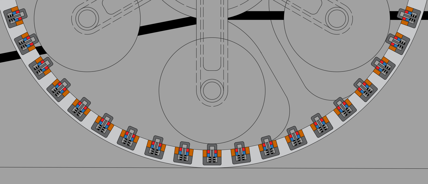
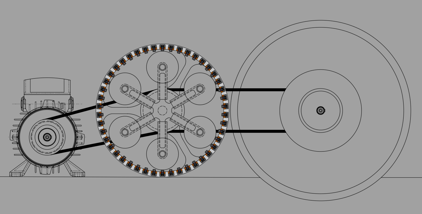
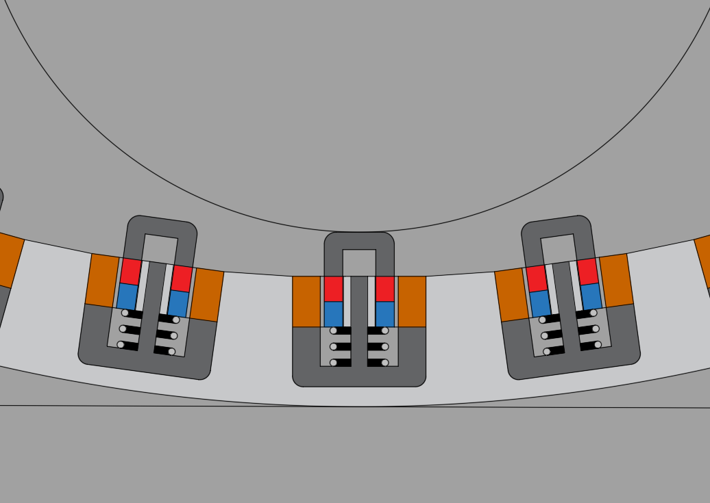
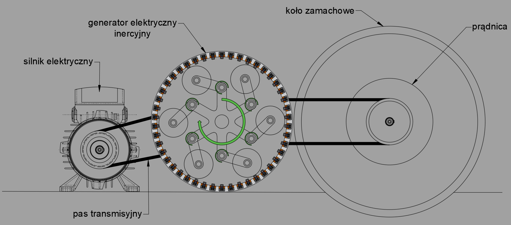
I catch an interesting idea lately after some earlier considerations of my other older device and I think this could be something worthy to show. This is inertial electricity generator based on centrifugal force acting on heavy steel rollers moving along and inside the external rim of special electricity permanent magnets and copper coils systems to obtaining electricity from electromagnetic induction. The electricity electromagnetic generators are located on circular track and are placed in external rim. They have two parts, and each have one compressive spring. The spring is used to actuating the position of the inside element after it is pushed inside external coil element. The system is equipped in six heavy rollers which are performing rotations inside the external rim and simultaneously performing rotations around their own axis, and they are mounted on ball bearings. The system is additionally enriched in DC generator, DC motor and heavy flywheel. If the system is to undertake the work, the preliminary start-up should be done by delivering the electric energy from external sources like battery or solar energy. Once the system starts to work it should continue the work even if external power is off. Then one can connect external receivers to the system and the device should continue normal work despite of adding the load. The system is energetically closed there is no need to deliver external energy to keep the device running.The centrifugal force is acting on the rollers and they are pushing on those electromagnetic two position switches and if any of rollers is move out from the switch the springs is pushing its cores to preliminary positions so the electric AC energy can be generated. The electric DC motor is connected to the system by a transmission belt also the transmission belt is applied to connect the DC generator with the rest of the system.The rollers are guided by the telescopic arms which are hiding in each other to allow the rollers to push on the switches, so they can generate the electric energy. Those telescopic arms are consisting of two parts. One is a part of central rotating rotor, and it is common for entire system also it is connected to central shaft and the second is the six pipes which are connected to shafts for each roller. In those pipes are moving the rods of central rotor. The electromagnetic induction generators each have one linear bearing. The arms have also two linear bearings on each arm. The drawing is cross-section of the system. The DC motor is not in cross-section, so it is visible. The cross-section is only on the main generator system. The drawings were prepared by me. The system is not showing the electrical connections between the elements. The coils should be slightly displaced toward the outside of the center of the device so the AC power should be better obtained. In showed situation the half current can be obtained.