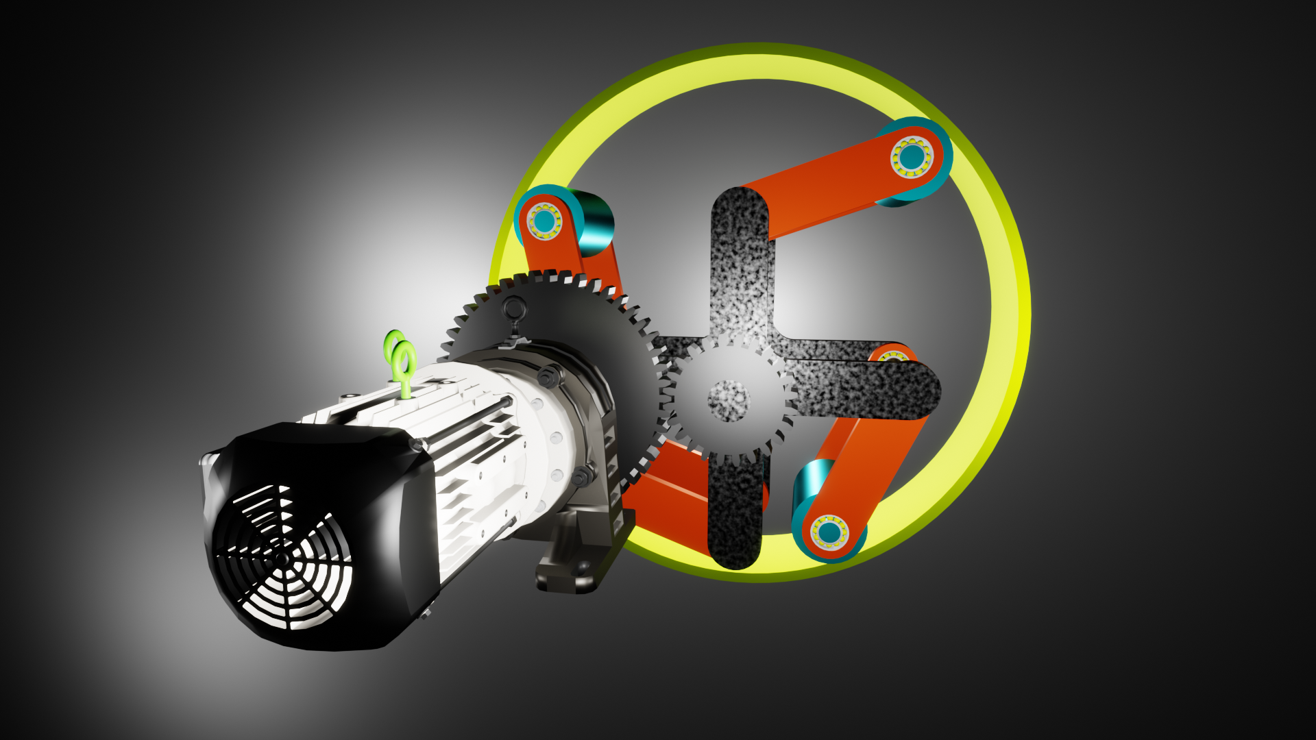
Inertial propulsion, specifically a propulsion system that derives its driving force from the rotation of specific components such as rotors and other elements performing other movements to create inertial forces that push or pull the entire propulsion system?a thrust generator using either centrifugal force or a force derived from reciprocating motion. This design has long been considered and, in its fundamental physics, does not contradict its canons. In my opinion, it is currently the fastest method for civilization to develop the ability to operate in the vacuum of space. This type of propulsor, combined with, for example, a nuclear reactor, would enable rapid exploration of space, both near and far, on a scale that current rocket propulsion will never achieve.
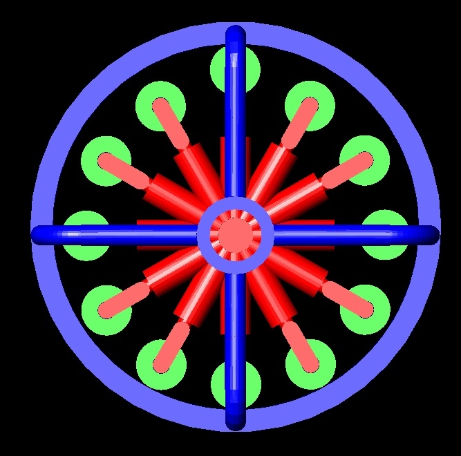
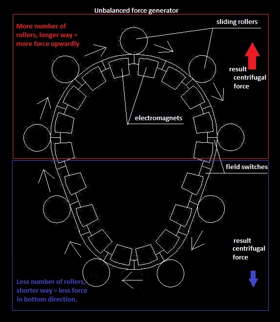
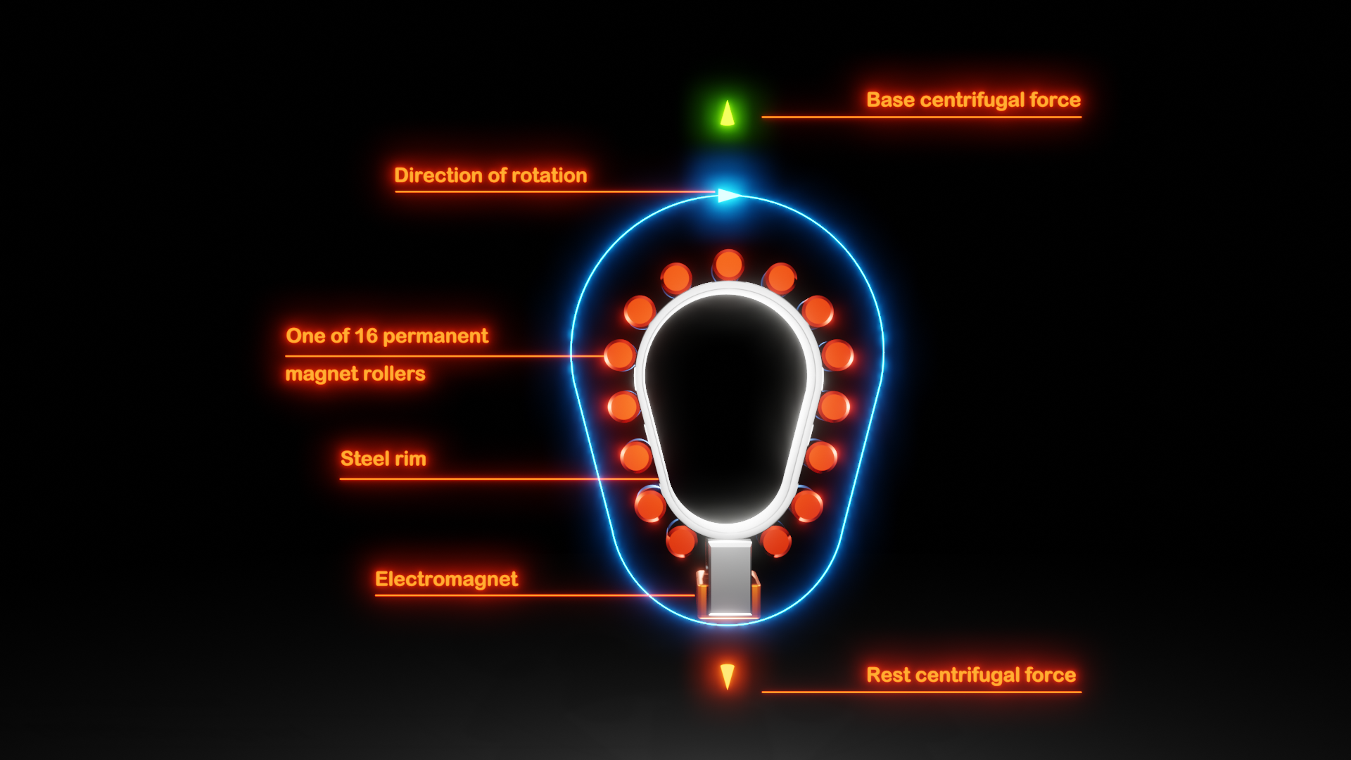
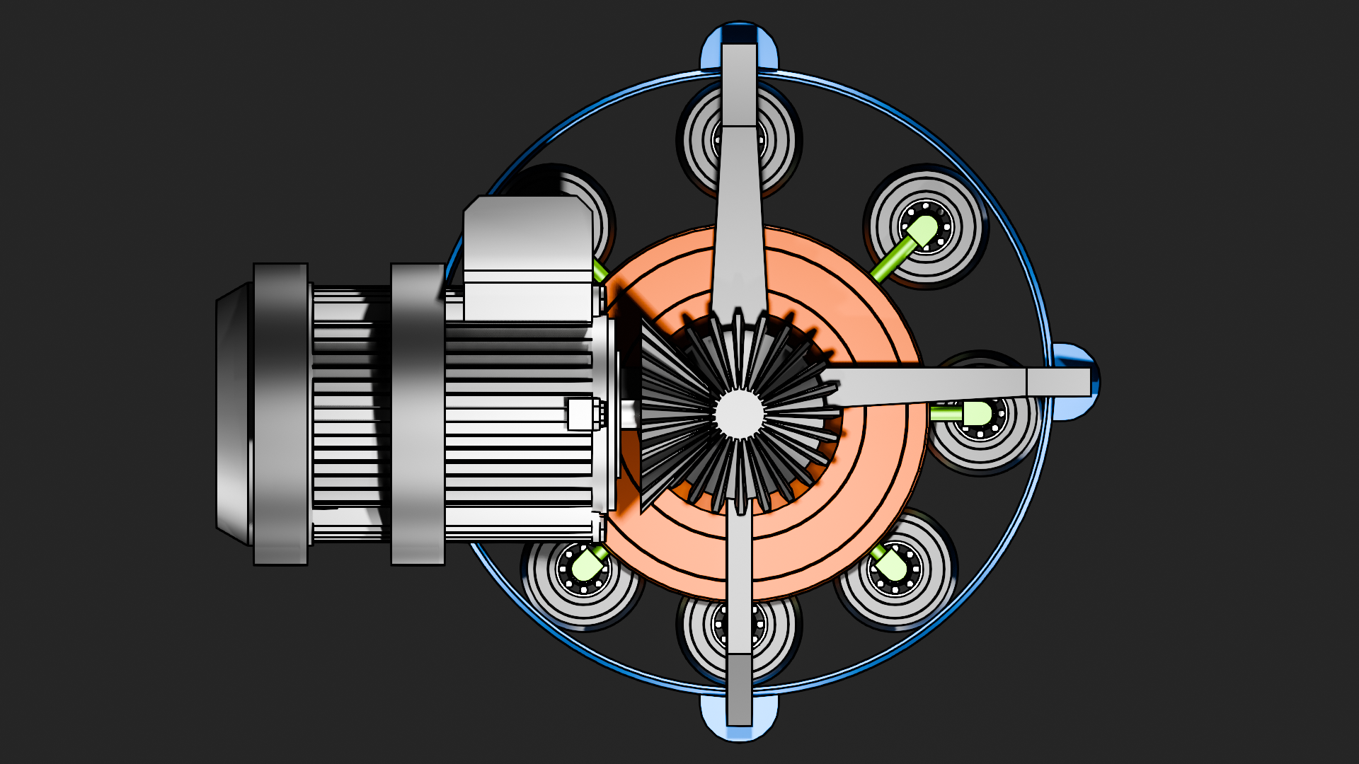
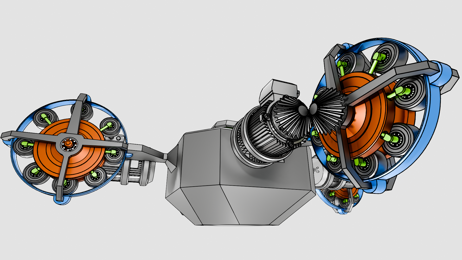
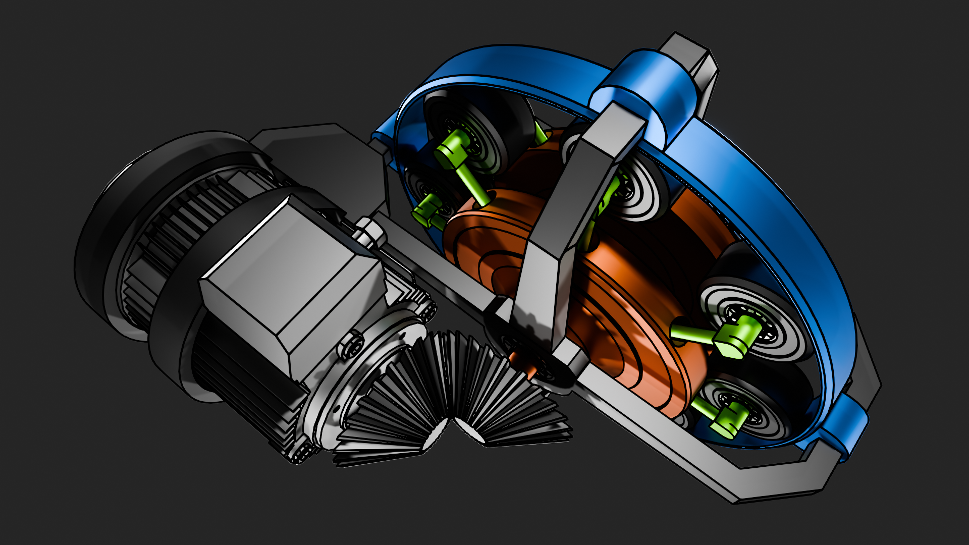
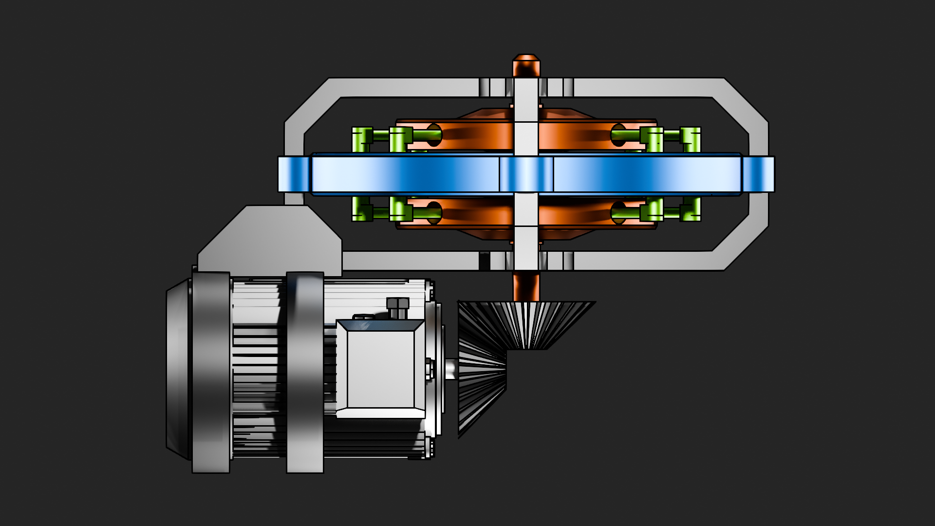
A drive using multiple rollers sliding on the housing from the outside, operating on the principle of having more rollers at the top in a given unit of time than at the bottom.
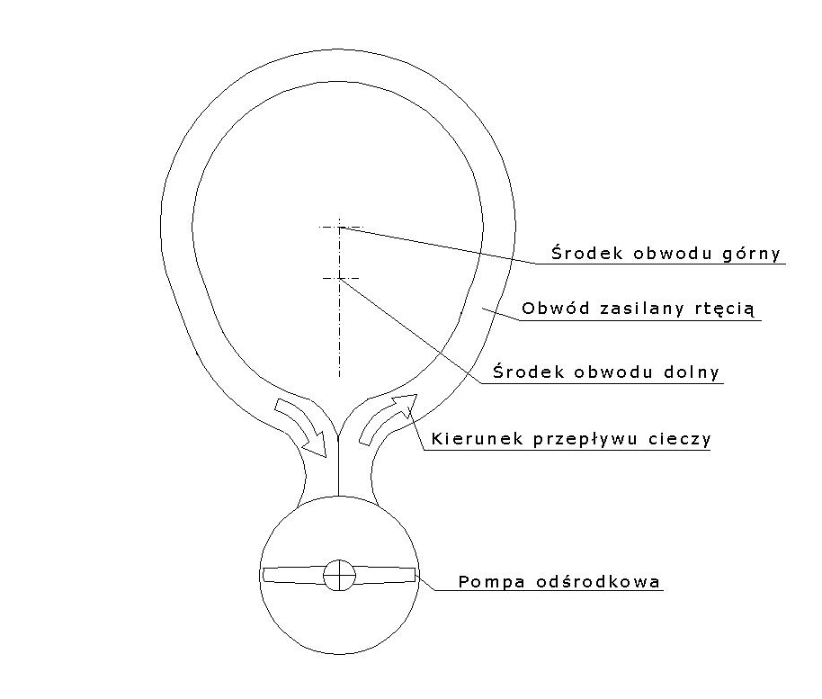
A type of inertial drive is one that utilizes the flow of fluids, such as water or mercury. In this type of solution, the driving force is obtained by circulating the fluid along a specific conduit profile, characterized by a difference in the radius of the top of the circuit compared to the bottom. This results in a non-uniform pressure gradient directed against gravity to achieve measurable driving forces.
A few years ago when I was at the beginning of my inspiration about space and technology, I was considering continuously something with application of centrifugal forces to propel robots and spaceships in space. However harnessing the centrifugal forces to propel spacecraft isn't something easy - every forces have opposite reaction in physic that we know today. In the inertial force which is connected with centrifugal force there is no separation between gravity force and inertia force obtained by rotation and this forces can't be recognize in most cases as different in appearance for observers. Forces generated by static mass which we call gravity are equal to forces generated by rotation which we call centrifugal forces. Now, the problem is how to apply this two forces against each other in the aim to propel robots and spacecrafts ? In the case of centrifugal force we have ability to obtain forces in every direction and the only one case that is necessary we want to cancel gravity is up direction. In gravity the force can't be changed and with the force vector aimed in the center of mass of the planet it is staying always the same. Some technics could be used to set apart the proper centrifugal force from another its directions against gravity in the case of reciprocating steel sphere as it is shown at the below picture. In bottom position the sphere has very low kinetic energy and in reality it is coming mainly from inertial impact, as the sphere powered by strong electromagnets is climbing upward the kinetic energy is getting bigger thus the sphere can give back its energy on the external case by the mean of centrifugal force, after that the sphere is falling to minimal kinetic energy again and the process is starting again generating linear lift. The generators should be at least doubled to the proper operation.
Roller inertial propulsion
Inertial propulsion
9 October 2024
Inertial propulsion
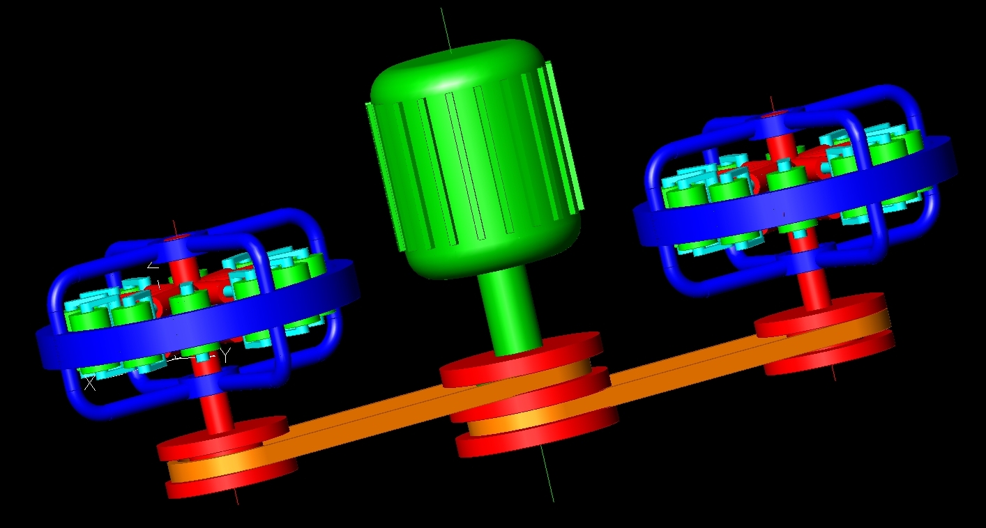
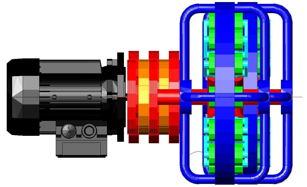
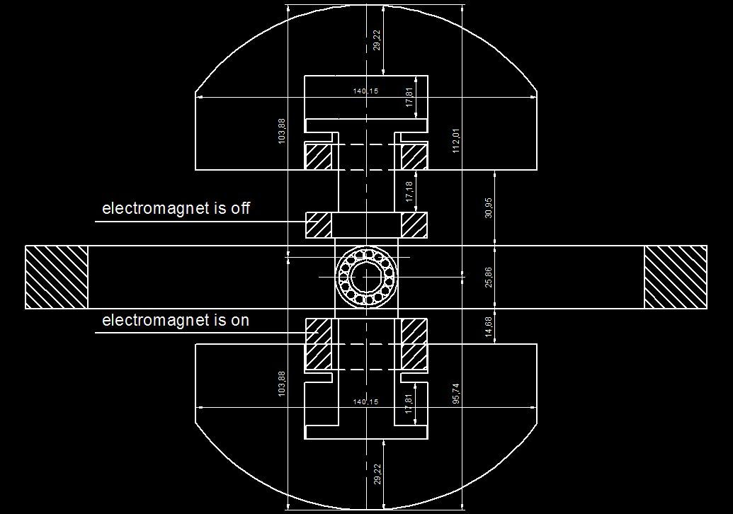
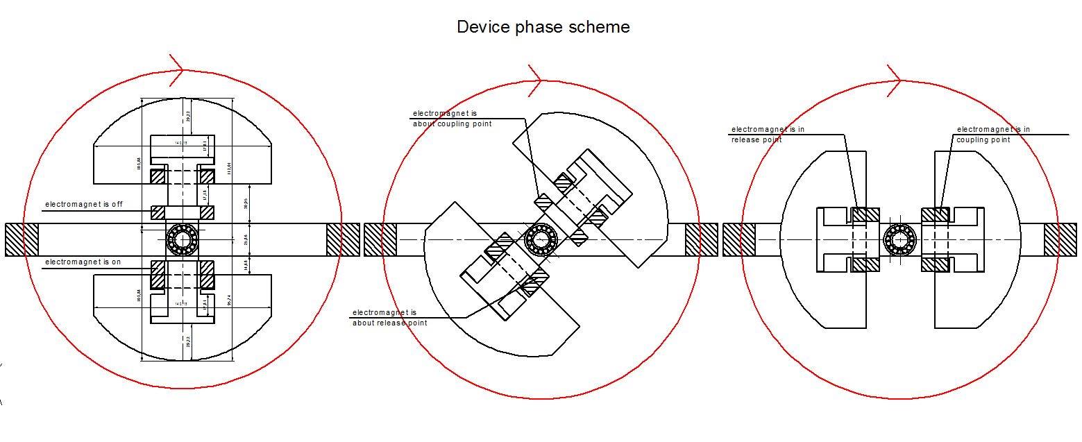
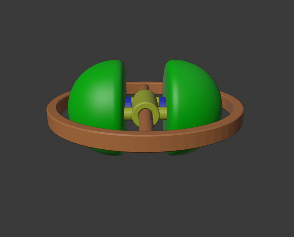
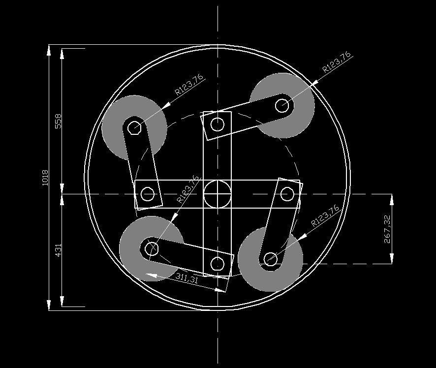
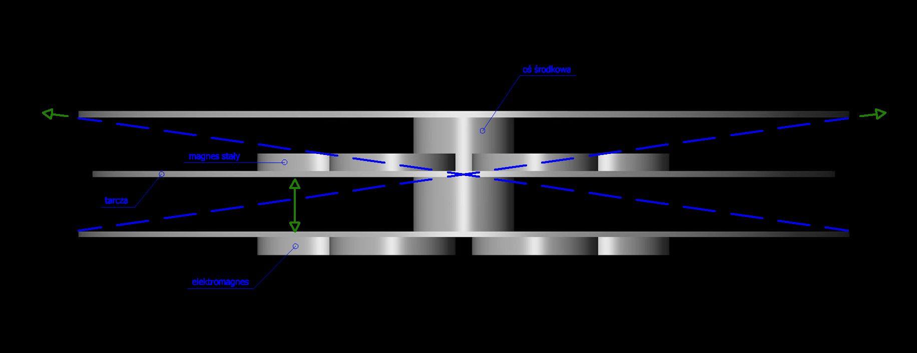
Below is a type of magnetically controlled inertial actuator. When positioned in the upper hemisphere of the rotor's rotation, the drive element achieves greater dynamics and inertial energy than when positioned in the lower hemisphere. This causes the device to generate an uncompensated force in the direction of the higher inertial forces with a longer arm. This device is ultimately designed to ensure that the distance between the holding electromagnets is small, preventing centrifugal force from separating the electromagnet in the lower position at any rotational speed. This could cause the centrifugal forces to become equalized and balanced, leading to improper operation of the device. This drawing is only a schematic diagram; it is incomplete and requires further work to eliminate any technical issues.
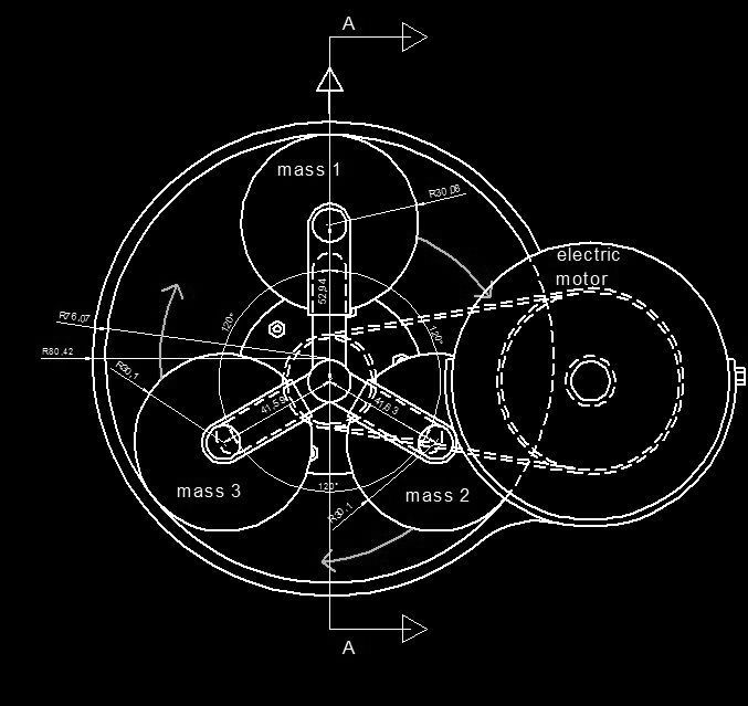
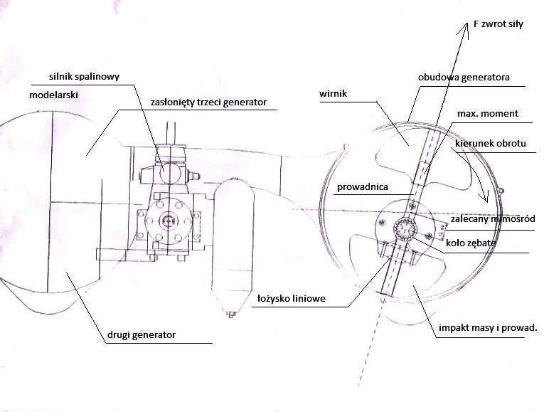
This drive method, although with features common to many of my later methods, has the characteristic that it is an early phase of inertial drive design, carried out by me back in 1995-2000, i.e. at the very beginning of my inspiration for this form of technology in MegaCad 1.5 Lt. I remember that I was simultaneously working on a project on another device in another CAD program, but it did not go as well as when using MegaCad and, as a result, I abandoned the second project in favor of a more advanced one.
Two masses - an early model
9 October 2024
Magnetic electromagnet propulsion
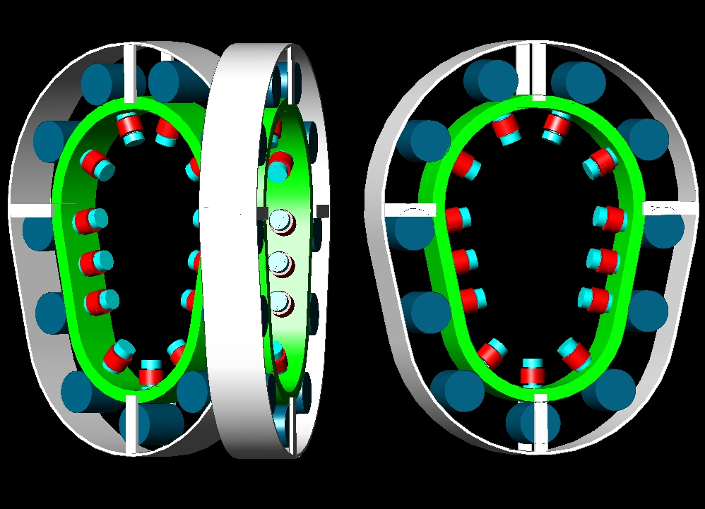
The operation of this device is based on magnetic attraction between the steel balls and electromagnets. In the moment the ball is on the right position, the electromagnet next to it is switched on, so it is pulling magnetically its mass ahead, simultaneously the centrifugal force is rising, the more distance from the center of rotation the more centrifugal force is created, so in the smaller diameter of the curvature the centrifugal force will be smaller than on the greater curvature diameter that is on the top of the each of three generators parts. The magnetic field must be disconnected each time the ball is abandoning the present commutator part. If the ball is on the right position on the commutator that is in the center of it, the magnetic field from the located next electromagnet is connected, so the ball is sucked magnetically forward, however it can't abandon the curvature thus its inertial energy coming from its weight and mass is redirected on this curvature from the inside. Although this system is symmetrical an asymmetrical centrifugal force should be created due to specific placement and inclination of three inertial generator. The result centrifugal force should be maximal on the 33 degrees inclination axis, and that how the generators are inclined, so it is not operating vertically. The centrifugal force is neutralized partially in the center of the device when the balls are returning to another cycle, but the main centrifugal force is not neutralized and additionally it is multiplied by longer diameter of rotation at the top of generators.
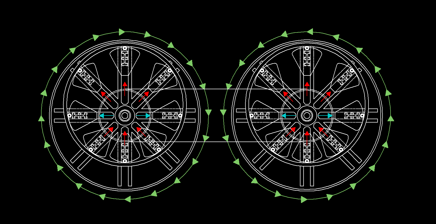
Rotor technology in which I have added some parts. This system should work on high rotational speed, however the problem of friction between rods and central wheel is still very crucial. The rods will be forced to move outside toward external rim by use of centrifugal force. They should have linear bearings or sliding rings and work on proper lubrication.Rotor technology based on centrifugal force distribution control. Like my earlier inventions this is also based on centrifugal force control. The system is consisting of eight rollers made from steel, each with double ball bearings on each side on main symmetry axis. External rim is predicted to make the trajectory to these rollers what with not centrally placed central wheel with profiled hollow ring in which the rollers have an opportunity to hide in bottom position during the movement around the indicated track. Why eight? Because eight rollers are most suitable for such a solution when three of them are in production of force at the top of the device simultaneously other three are in lowest position and there is no asymmetry in the system beside the required asymmetry in up - down direction, as usual two rollers are inactive for production of force. The central wheel with profiled groove around is in 'H' shape in vertical cross section so the rollers can hide partially in this groove.