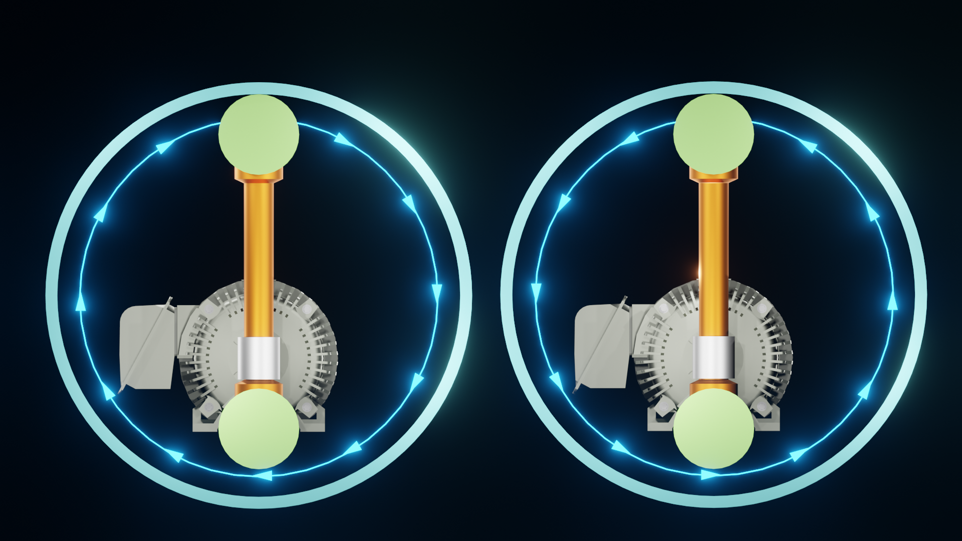
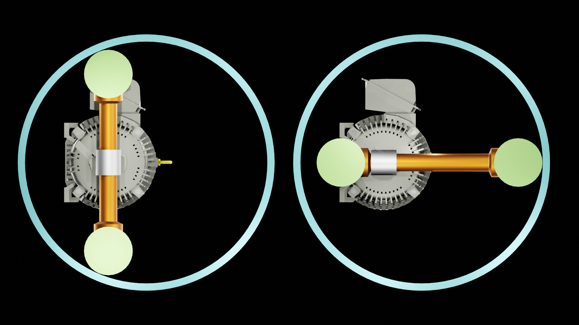
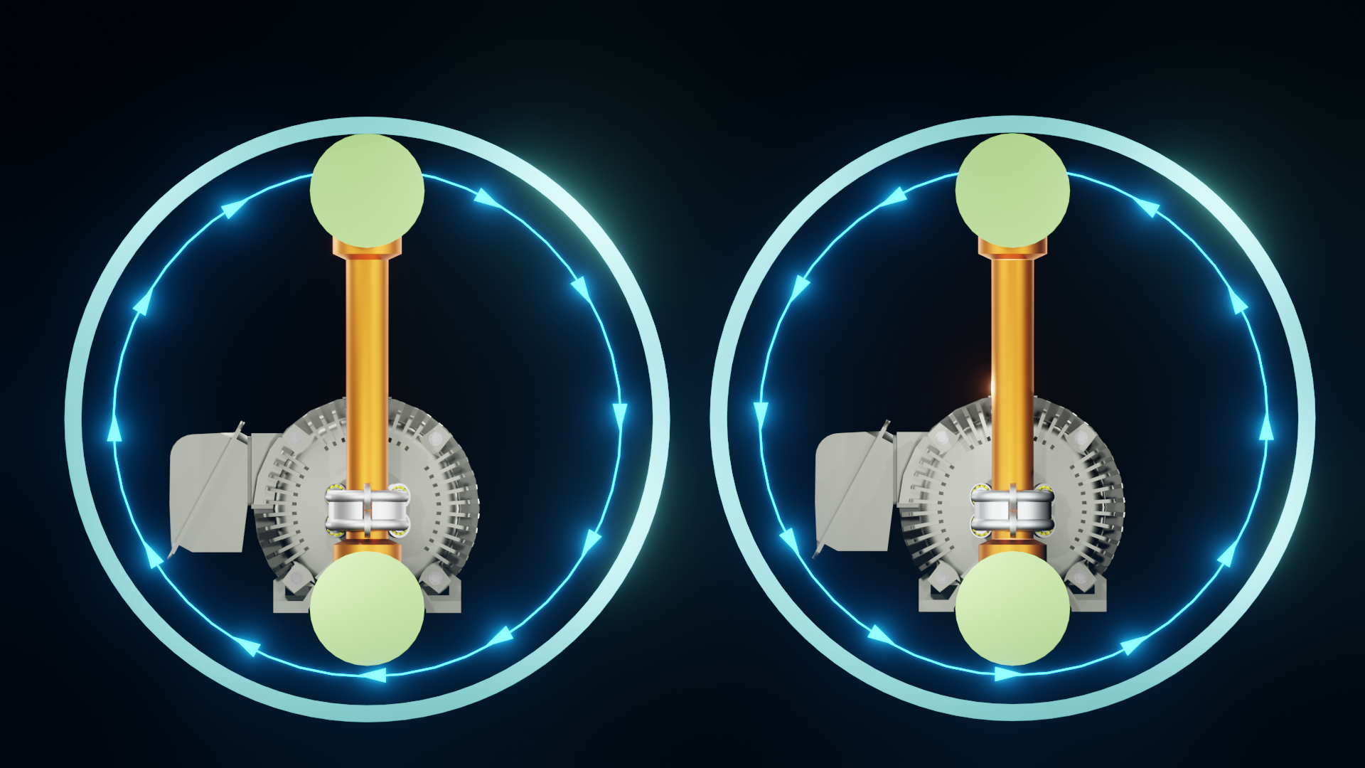
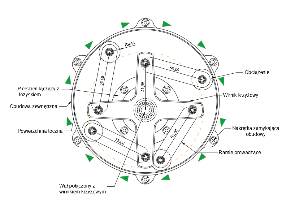
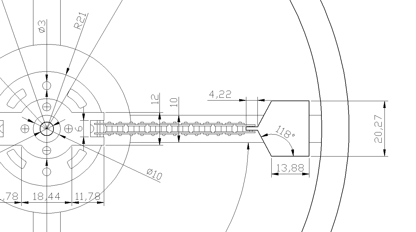
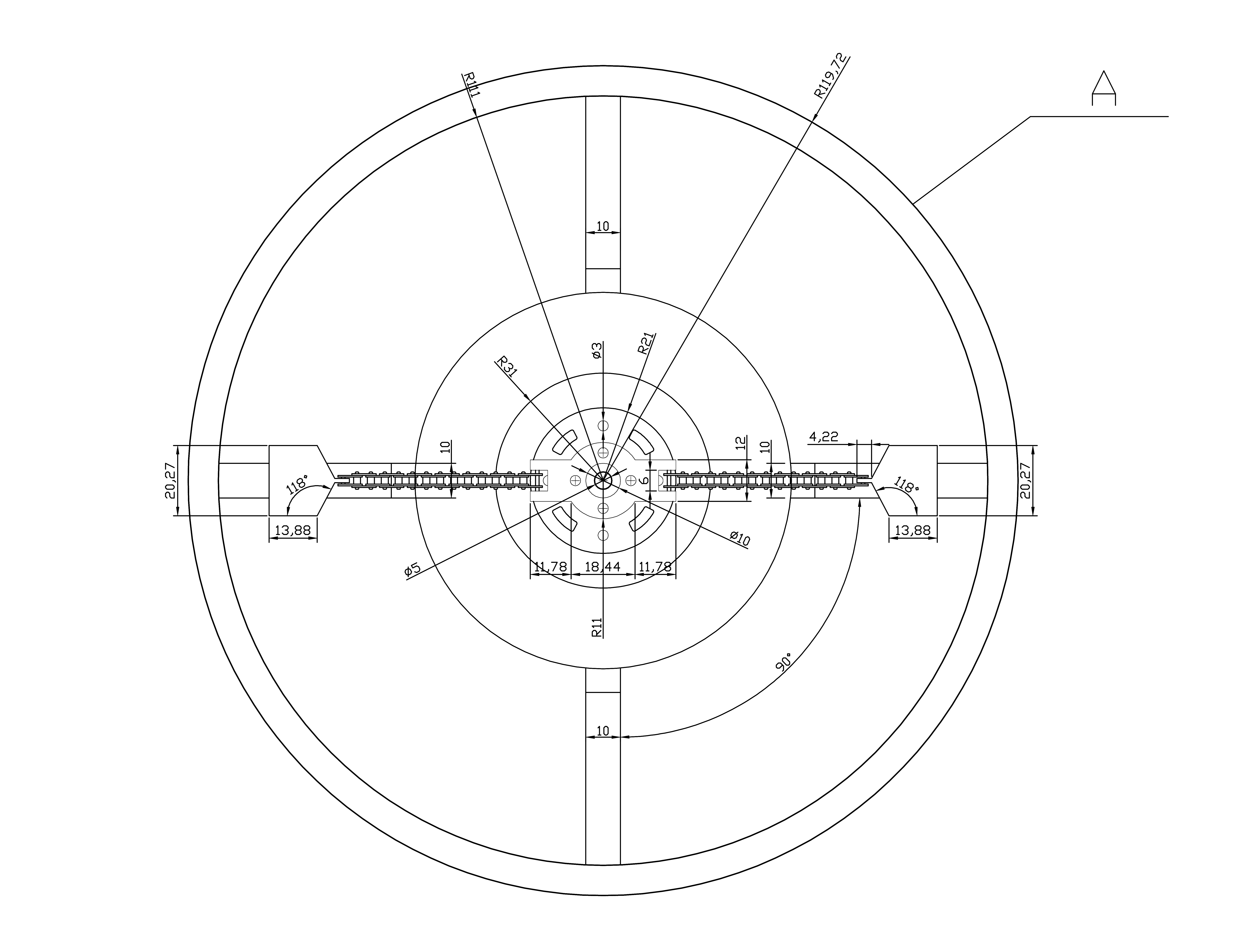
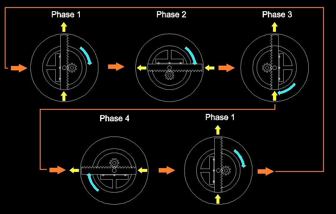
Is space travel always associated with rocket flight? Not necessarily, because the answer to rocket technology is inertial propulsion, which can work as shown in the diagram below. Depending on which mode we are dealing with, the diagram can be interpreted differently. In phase 1, the shaft is in the upper position and delivers inertial energy for propulsion. If one wanted to achieve propulsion through centrifugal force rather than the inertia of the shaft's return, the shaft should be drawn in the initial position tilted 90 degrees relative to the vertical, i.e., the situation from phase 1. However, I probably initially thought, when drawing this operation diagram, about the self-inertial mode, and later also considered the centrifugal force mode, which may be misinterpreted - this was due to the speed of drawing this diagram. In the case of the centrifugal force mode in the operation of the device below, the shaft is never shifted to the lowest position, which results in the eccentric always running in the upper zone of the device. Then, in the shaft position defined as horizontal, the shaft extension shifts in the opposite direction, and the situation repeats infinitely, so the force is always generated only at the top of the device, which is why the device can propel any vehicle in space without emitting exhaust gases like in a conventional rocket. In the case of the inertia-only mode, the device operates with an inertial pulse when changing the direction of the working shaft's movement - the pulse occurs once every 360 degrees of rotation, i.e., every 180 degrees, because the shaft operates in a double manner. However, with the rapid operation of the rotor changing the shaft's orientation, the force from the shaft's work stabilizes and becomes smooth. The device diagram and idea were created "on the fly," so it is possible that I messed something up, while the idea itself may be correct, the whole thing probably still needs refinement. It is probably also necessary to consider whether the device should operate duplicated with the same but counter-rotating and synchronized rotor with an oppositely acting shaft, to avoid so-called unpaired moments. Someday I will properly draw it in ZW CAD when there is an opportunity, but for now, the device is promising but looks as it does. Greetings to all researchers and friends who tried to understand it.
Inertial propulsion
>
5 May 2021
Centrifugal drive. The green masses rotate around a central axis, driven by an electric motor. As their deflection increases (centrifugal force pushes them slightly outward and upward), they pull, via springs or flexible links, a lower disc-orifice attached to the central axis through a sleeve that rotates with the springs.
Inertial propulsion
Inertial propulsion
2. Simplest inertial drives.
5 May 2021
One of the simplest inertial drives consists of an electric motor, a through-shaft hub, and the freely positioned shaft itself, along with an outer housing. This video shows the shaft moving, forced into rotation by the motor and corrected by the outer housing. As it approaches its final rotation, the shaft has already acquired sufficient energy to no longer require control from the housing. If the shaft were slightly more precisely adjusted (the drawing was created without prior calculations, based solely on intuition), it could slide literally within the housing, but it is important that it has the freedom to transfer this inertial energy to the housing and, consequently, the entire system. A complete inertial drive should have at least two or three such sets. The issue of friction remains an open question; in the presented form, it is not resolved. The shaft's tips press against the housing, which can result in it carving scratches on the inside of the housing, or even burning the entire assembly from the frictional heat. The lubrication method for this device, whether it will operate with grease or in an oil mist, is an open question. Grease or oil can escape due to centrifugal force and lubricate the entire device to prevent ignition. A specially designed dense needle bearing (with needles on the inside) can also be used around the perimeter of the device. If the radius of curvature of the shaft tips were appropriate and the shaft were slightly widened to ensure contact with the bearing needles, the entire unit could operate better.
5 May 2021
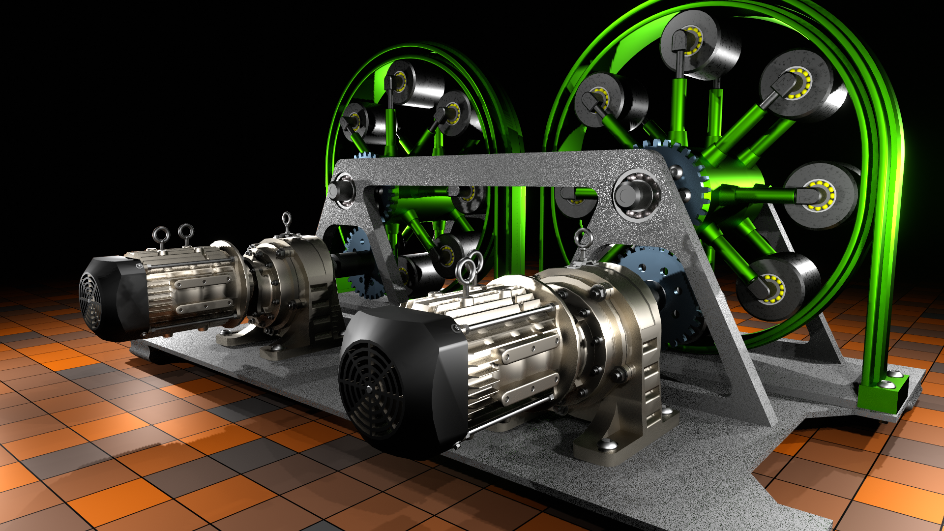
Other mounting and guidance of the central shaft - ball bearings have low rolling resistance, such a through hub with ball bearings arranged in two rows at 120 degrees to each other. I have the impression that if a linear bearing were used, the rolling resistance would be too high, resulting in significant friction and, consequently, temperature. It seems to me that using ball bearings would slightly improve the ability to move this shaft/central sleeve. As for the point of the central rotating pin holder, it still seems that for smoother operation of the device, it should be a little closer to the geometric center of the system, which can be easily corrected by moving the holder with the motor or the housing in the opposite direction. Someone may have noticed that the system is paired, this is to reduce or completely eliminate vibrations and so-called "runout," if the system were not paired, this runout would lead to the destruction of the rotor and the entire device. When the system is paired and additionally synchronized, so that the rotors work in pairs, but rotate in opposite directions. Someone may also have noticed that there are two motors - there should be one with a split to two generators, because in practice it would be difficult to synchronize two separately operating electric motors. So through gears, I plan to distribute the torque so that there is no possibility of unsynchronizing the system in an uncontrolled manner. This design has several drawbacks, primarily the mounting through the hub, secondly, that the outer carts do not rotate in a position close to the hub/center of rotation, there is no pressure on the rim in this position, which may slightly slow them down before they reach the friction surface at the top.
3. Hop experiment with application of the coil and permanent magnet.
5 May 2021
The experimental set consists one copper coil, one permanent neodymium magnet, and suspending construction formed from two cd plates, and brass distance elements with screws and plastic joints which are keeping magnet on the right place. This system won't be working in vacuum condition, needs desk under itself to operate. Maybe I will find in the future the way to run this device as a independent propulsion method. This is not Lorentz force based experiment but only inertial force obtained from interaction between the magnet and the coil which is acting on top cd plate, but also acting on this plate half a power is dissipating on the workshop desk. If someone wants to obtain real propulsion in this case than the result force should be asymmetric. However according to H. W. Bull experiments with electromagnets in his reaction impulse engine some force must be dispersed and some force must be increased and he is obtaining this by application of springs. In this situation the jump gap is too small, the interaction between magnet and the coil is too weak to compress the spring and the system need to be doubled by other system with contrary motion direction, those conditions are not met. The second problem is power supply of AC square current, all the devices which could to generate such a current in my workshop have too less voltage, the best generator that I have has current protection and doesn't give the current on nearly short circuit condition. The battery is getting hot during using. Maybe if the coil have longer wiring the system will start working better. Earlier I was showing the jumper experiment which was successful and was based on the same principle, however the movement was in horizontal plane, the coil was on the 45 degree angle to vertical axis but the system was working pretty good and the displacement was about 15 cm on the whole working scale. I have thought also about application of transformer that would be plugged into the wall socket and the whole thing would be work with 50 Hz frequency, however this frequency is too big for this application and additionally I can't make it less or bigger in this case. So I'm going to build my own generator of pulsed current with regulated frequency ability based on very simple components thus they won't get damage if I will overload them.
4. Simplest inertial drives.
5 May 2021
A simple inertial drive which seems to be easy to do in home condition or in small workshop. The entire system is consisting of four steel balls, external ring, one cross pipe and electric motor. The main principle of operation of this system is that the balls have free space for extend outside cross pipe and they are rotating on asymmetric trajectory in vertical direction - ex- center location of cross pipe, so on the bottom they are hiding inside pipe and on the top position they are extending from them more so the centrifugal force is stronger on the top because the balls have more kinetic energy on the top as they are moving with greater velocity than on the bottom what is caused by less distance from the center of their rotation on the bottom than on the top. The balls have also enough space to rotate inside the cross pipe however some friction will be appearing in this system. This friction can be decreased by the use of brass rings instead the bearings placed in each end of the pipe.
5 May 2021
A scheme of an inertial propulsion system with two masses as a load to obtain unbalanced centrifugal forces. Each of the two masses have one ball bearings. There are also two linear bearings sliding inside of each caring, open on entire its length, rods and they are moving along in both directions. At these linear bearings there are welded short rods for ball bearings. I also considered the system with four masses what also could be here applied with success and in this case the acting forces would be doubled - the frequency of mass-energy exchange would be two times greater than in the system with only two masses. However adding too many masses perhaps more than four would be resulting with much changes in construction of the device in this form - the center point of rotation of the two directional hollow rods should be placed more centrally with respect to external rim.
5 May 2021
This propulsion system that I noticed one time on Alfred Evert site back in 90' or slightly later was in fact only a 2D drawing with additional ball bearings on the top of each weight. As a latest version I will make an animation in blender of similar system with a little different constructional assumptions. The main change rely on the change of smal ball bearings on the top of each mass on big needle bearings inside the external rim. Previous version was similar to this scheme:
5 May 2021
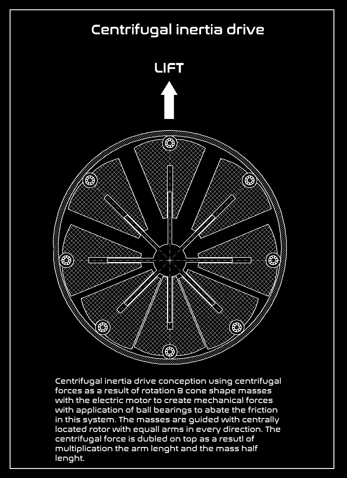
An idea of rotor technology that I predict to use in my inventions. The rotating weights have one or two ball bearings on each end sliding on internal surface of external rim helping to avoid friction. They are carried by rods which are passing through them along and inside in drilled holes for this aim, which are rectangle in cross section. Central rotor has eight arms, and they are passing through the center of each weight in drilled holes for this aim, they have bearings too and this is a specific system of bearings which here is not visible. This system is predicted and optimized to convert centrifugal force during the rotation of the rotor, to linear up aimed force for overcome gravity acting on entire system - hypothetical vehicle, which will be consisting of several such an inertial propulsion system. This system is simulating antigravity, but it is not antigravity propelled. This system is more plausible because it is oriented for obtaining maximal centrifugal force coming from the specific shape of each weight (most of the mass is located on the ends of the weights maximally far from the center of rotation so it is located in the right place for obtaining maximal centrifugal force during the rotation of the system). In case of the roller-based system a part of mass is located near of the center of rotation of the generator, so the system with conical weights is probably better solution if someone is willing to obtain the inertial propulsion force from rotation of the weights. In the case of conical weights rotor, in lower part of the device, the weights are near each other, and they are close to center of rotation, so centrifugal force should be weaker than in upper hemisphere of rotation where they are on far extension. I need bigger CNC milling machine for making a right scaled prototype because this milling machine that I have is allowing me right now for making only small parts and is not suitable for machining of durable steel. I need to rebuild my workshop for more complex goals. I will try to build a drone consisting of three such generators with additional control of electronic equipment and electric motors as a main source of mechanical force.
5 May 2021
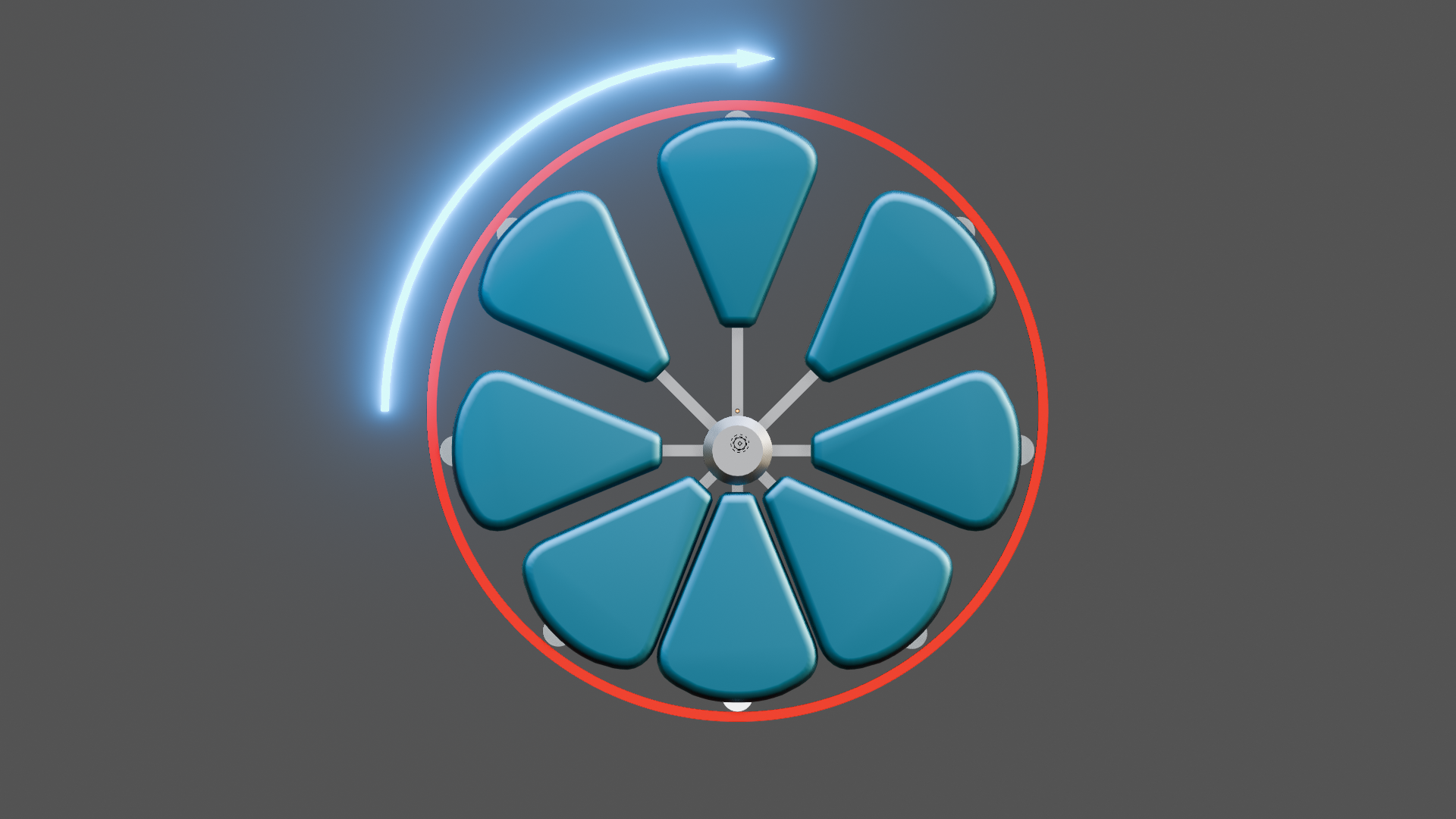
At the below animation that I made in blender 4.1 for better understanding what is going on here if we consider inertial and centrifugal forces, I am presenting movement of weights during the rotation of the system of propulsion. If somebody have proper software one can calculate and simulate physical relationships and tendencies in such a system. This system is on maximal usable extension in upper direction, so it can block itself if the bearings will be not properly applicated. The extension should be not so big for smoother working of the device. The device is almost optimal but naturally could be a little improved if somebody has more data and is able to calculate the proper dimension and relationships.
5 May 2021
On above picture is shown several weights rotating on central rotor shaft with many rods, on each rod is moving one the weight. The picture is simplified. System has mechanical energy supply by external electric motor. The weights have linear bearings between rods and itself what is not shown on this picture.
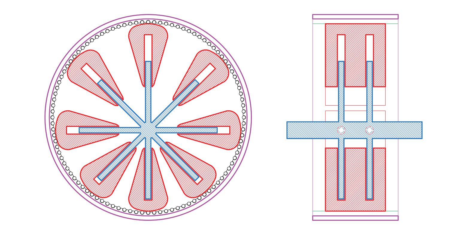
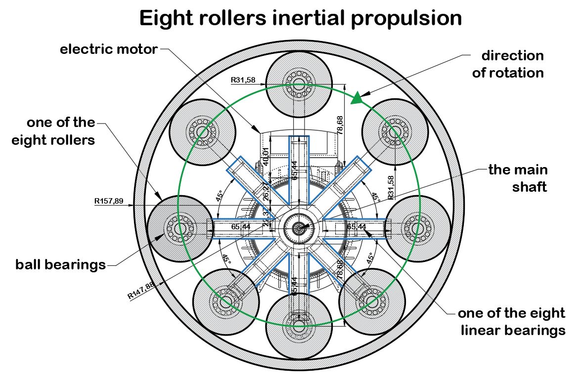
I've added also electric motor which is delivering the mechanical power to the system. Another big change is making the weights as a doubled masses connected by a rods to obtain more geometrical and functional stiffness to avoid uncontrolled rotation of the masses on round rods, making it double with connection allows to avoid this problem and increasing the weight mass at once two times. The quantity of rotating masses is eight. The system have also linear bearings inside each of rotating mass in number of 2 for each pair of weights. This propulsion have additionally rounded corners as a finish of the weights what allows for a better sliding of the weights on the needle bearings.It is recommended to apply some lead fill in the inside of the weights for make better parameters of acting forces, however it is not necessary because the weight of steel is enough for this solution. This system should to operate with a greater speed in comparison to the system with more ex-center placement of the point of rotation as is seen in previous scheme. I applied here less ex-center solution with more respect for greater speed of rotation and bigger rotating mass for less vibration reasons.The system if right constructed could give a lot of power and should be able to lift heavy loads, crew and equipment. However the main obstacle in this case to obtain an efficient working prototype is the lack of financial support for starting crucial works on this technology. Rocket technology needs a dangerous fuel and liquid oxygen. What we got here is a propellant-less clean propulsion method capable of eliminate every jet and rocket transport and it is a simple inertial propulsion system as a many I was presented lately unfortunately having only a hope that someday this propulsion will see the daylight for good of all mankind.
5 May 2021
This propulsion is possible by taking to knowing one simple fact, that is the rollers which are closer to the center of rotation are moving slower than the rollers which are on the point of faster rotation. In this propulsion method three rollers on the up position are on the faster rotation phase and three lower rollers on the bottom are on the slower rotation phase, the two side rollers are neutral on constant turn of the device. The device is projected for fast ratation, the extending of the weights on upper position and in bottom position can be solved by application of displacement of the location of external ring relatively to the center of rotation of the rotor thus this is the shortest way to control the power of the device.I don't need to notice, that with the faster rotation more centrifugal force is appear thus on the three upper rollers is acting bigger centrifugal force than on the three lower, so this system produce linear force against gravity - load can be lifted and this propulsion can to propel spacecrafts in space conditions.
5 May 2021
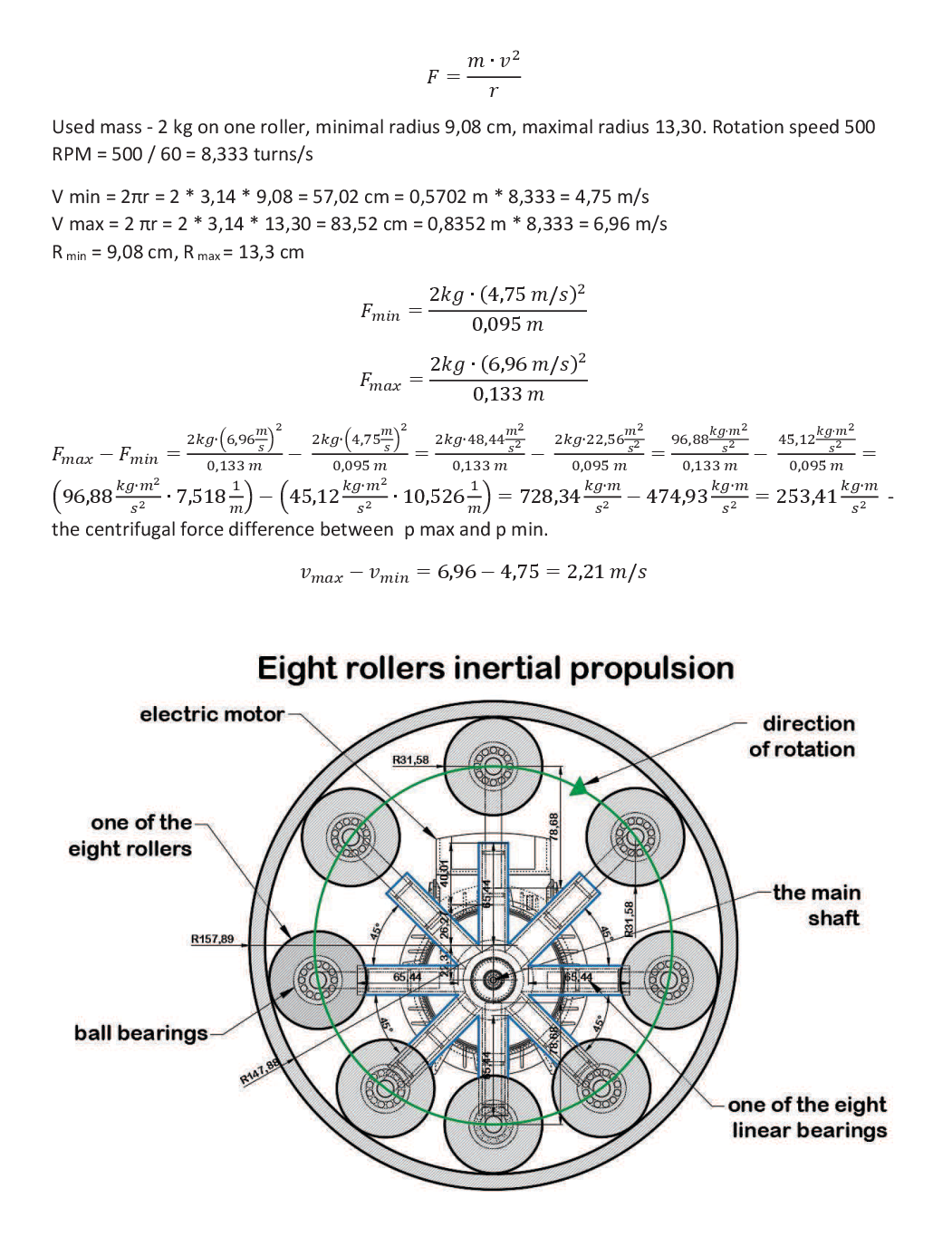
I did some calculations on eight rollers inertial propulsion. Whether they are correct or not, it remains to be seen, in any case, the calculations show that the difference between the centrifugal force at the top of the device and at its bottom is 253.41 kgms-2 that is 253,41N, the difference in the speed of mass movement in this case is 2, 21 m/s between these two points. These are the results based on the assumption of a speed of 500 RPM and the values read from this section. The difference in the radius to the center of mass of the roll. The pressure of the roller holder on the telescope is not taken into account and it is also quite a large value and translates into the total calculation weight. I determined the weight of a single roll at 2 kg, but it would have to be precisely determined whether there would be no discrepancies with these dimensions of steel rolls, because it is an approximate value. The value of the total centrifugal force should include the value of centrifugal forces arising from other rollers in the amount of two additional ones, which, however, will have a slightly lower force, because they are at an angle to the vertical and their radius from the center of circulation is also smaller. Two rollers on the sides, whose forces balance each other, are insignificant in terms of calculations. The three lower rollers are at minimum radii and their instantaneous centrifugal forces are close to the calculated value in the low position of the device.
5 May 2021
Permanent magnets polarization. I considered also using electromagnets (horse shoe electromagnets). Unfortunately I don't know how I could calculate if it would be working or not. The system seems to me to be not correct in its main assumptions in this form, maybe need some modifications. The existing point of suspension is not allowing for such a device to be working with a main assumptions. I think that the centrifugal force will be not decreasing the weight of the device during its work due to the point of suspension which is not affected by the centrifugal force in this case. I am always really willing to find the answers in the inertial propulsion matter so I will try everything what make me closer to the true inertial propulsion systems to let this become a reality of terrestrial and space travel so this is only another attempt in this research which not necessarily at this time can lead me to a proper solution on this road. This system is pretty simple but whether the centrifugal force is work in this way, as the animation shows, I am not convinced. If I be able to build a working model of an inertial propulsion it is more probable that I begin rather from an ex-center machines than such a devices.
5 May 2021
Human race is endangered by extinction not only for its own activity. We have to do a lot if we want to survive on this little rock - planet Earth. For that reason it is not enough to do what we have been doing until today, we have to reach for non - standard technologies like for instance inertial propulsion and gravity propulsion.to spread our technology and life in entire galaxy. This aim is not possible to obtain by using conventional technology means. I know that someone can question inertial propulsion as a proper technical way of transport for the reasons which our science know very well. But I noticed that lately the science approach to inertial propulsion is in many topic points more enthusiastic. More articles in Internet and local press is describing new space transport conceptions. In space there are no fuel stations and rocket transport people are already know that fact very well for sure. So making a step in the direction of inertial drives seems to be really reasonable. I've written a lot already about inertial propulsion method useful in space and today I'm not going to stop to do this because other propulsion systems seems to me more distant to realization than inertial propulsion, no rocket propulsion is good enough if we take its propulsion parameters to consideration. The best and who knows if not only solution seems to be just inertial or gravity propulsion. The gravity propulsion isn't yet better described by anyone until our times. We have WARP drive basics but for now frankly saying WARP drive is more similar to fairy-tales than to real propulsion method. And probably for that reason I noticed that inertial propulsion works even if these are only toy-like solutions and nobody saw working toys based on WARP propulsion yet. However if to add much more attention to this technology problem the inertial propulsion basics seems to be much more clear and obvious solutions than some of old well-know technology we use since even a couple hundreds of years, the only problem is money and time to develop this technology.
5 May 2021
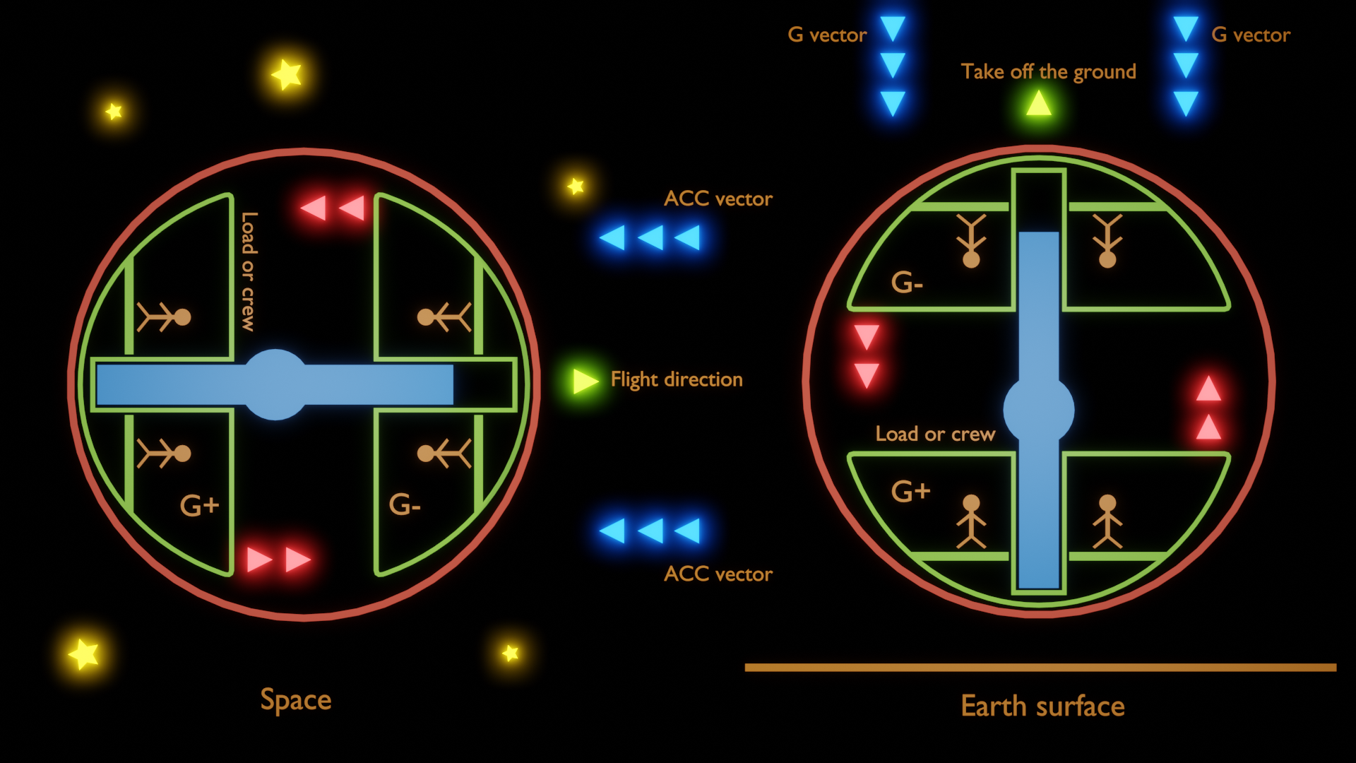
Especially time is here most important factor, because we have no time already to spoil as a civilization. Considering such a topics as economy, pollution of the environment, social problems, we cannot afford for waiting for such a solutions as are presented by SpaceX or Blue Origin. Only mad people could trust rocket technology, knowing every limitations of it. In this limitations set the main place is occupying the lack of possibility of turning back to Earth during the mission. The vehicle without the propellant is useless that's the final limit of rocket technology. To the future belongs the propulsion method where there will be no need to refueling the tanks to fly further. That's the moment where inertial propulsion comes in. Inertial propulsion also needs energy to functioning but what we have here is disconnection the main propulsion factor from energy delivering method and this is the main advantage of inertial propulsion in comparison to rocket propulsion where there is not such a possibility. In inertial propulsion method we can propel the system with electric energy using electric motors, in rocket propulsion the only way we can use electricity to propulsion is ion propulsion method and as we know well ion propulsion gives very small thrust to less to start from the planet surfaces. Inertial propulsion is a method of propulsion that it will be an opportunity to start from the surface of Earth and Mars as well as Moon. Inertial propulsion is decreasing gravity vector acting on some propulsion elements on the deck, so it can lift of the ground in state of over the state of weightlessness, which is the point where inertial, centrifugal force gradient change is equal to gravity local gradient. The inertial propulsion is thus allowing to obtain thrust from rotation of heavy internal elements when the inertial force is surpassing the gravity force so the generators can lift of the system upwardly despite the fact that the gradient of gravity acting on passengers inside the ship stay the same. In some system of inertial propulsion I was described the system with entirely fixed the problem of diversification of those both gradient acting on the generators and the passengers by locating the passenger compartment in the middle of propulsion system in the way that the mass of passengers would be in rotation state and sustain the mass of propulsion for entire spaceship. This was to sustain the proper g conditions on the deck and getting the acceleration by the spaceship.
5 May 2021
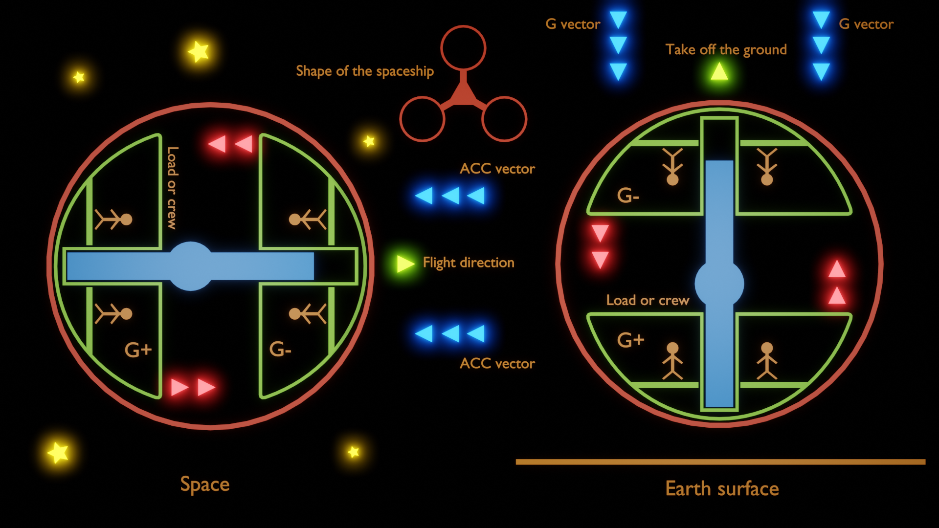
In below solution the passengers are present more time in front part of the spaceship, that is the side complying to the movement direction than in rear part of the vehicle. The whole cockpit is rotating in one direction and it is once in rear part of the spaceship and once in front part of it. However if the cockpit would be rotating with a great velocity than even vibrations will be decreased to the minimum. So once the rotor is rotating the spaceship will be obtain propulsion and additional G eliminating to the right level even if the spaceship will be moving faster and faster. The force of acceleration will be balanced by centrifugal force.
Similarly to this assumption if the spaceship is to start from the Earth surface the centrifugal force will be decreasing gravity force acting on the crew until the spaceship will gain a proper rotation speed to take off the ground than the crew will be affected by several stronger force than being in the rest on the ground but this force will be dependent from rest mass of the part of spaceship which is not in rotation state, because there will be such a mass for sure. For better balance there is the need to pair the main rotor with the crew another the same rotor with crew or with the deck load the same in mass as the first.
5 May 2021
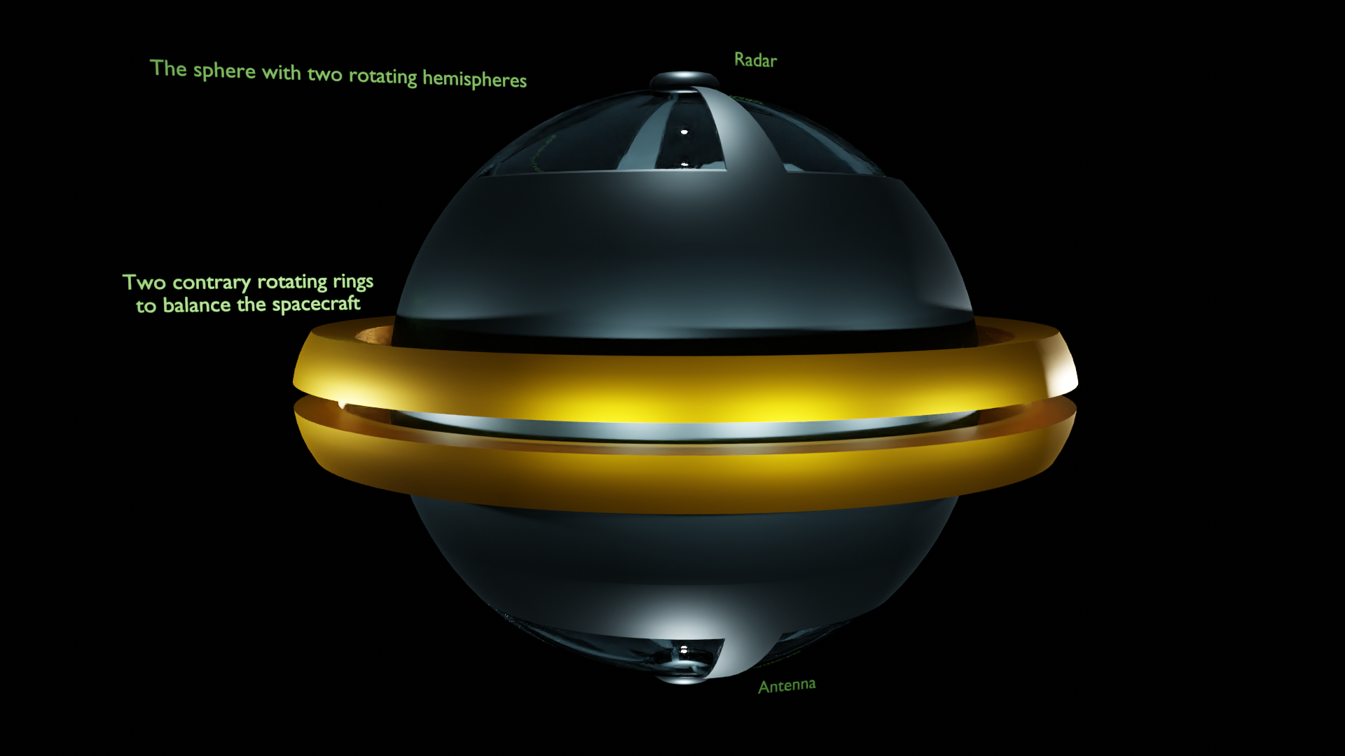
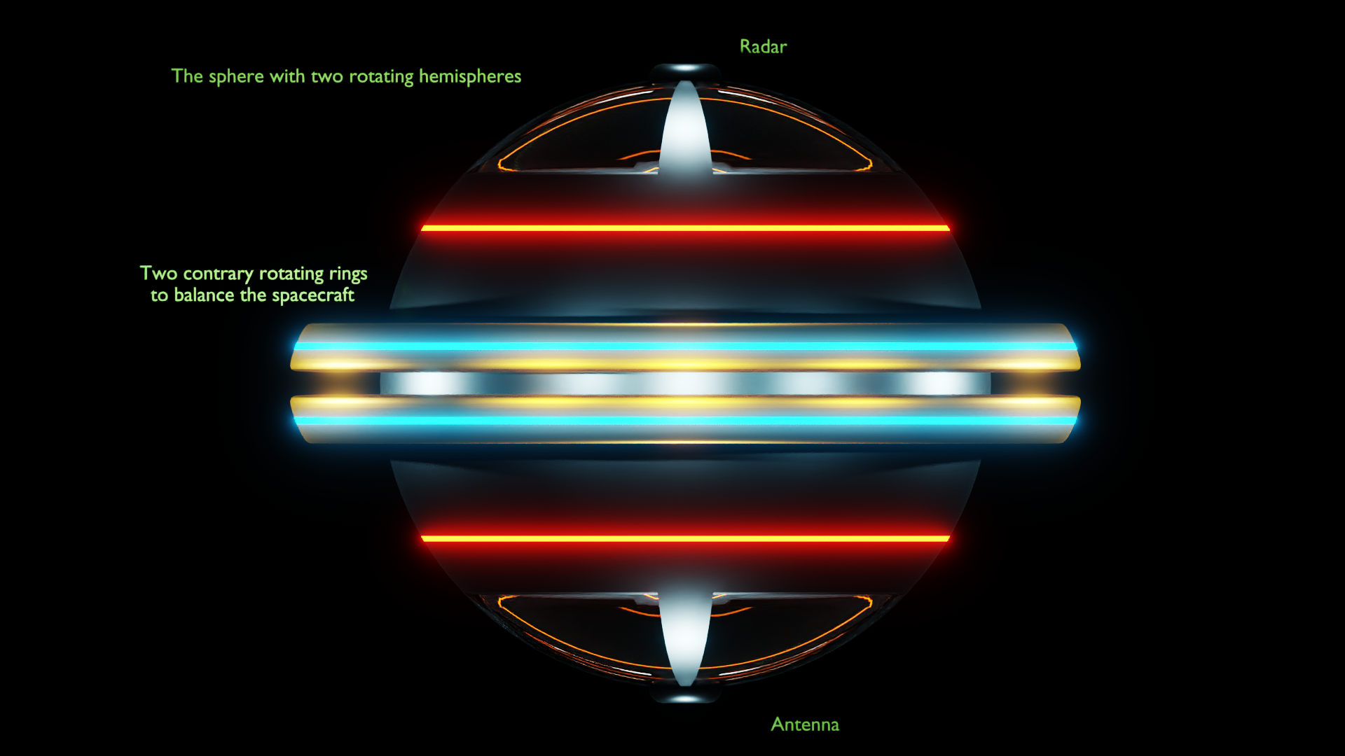
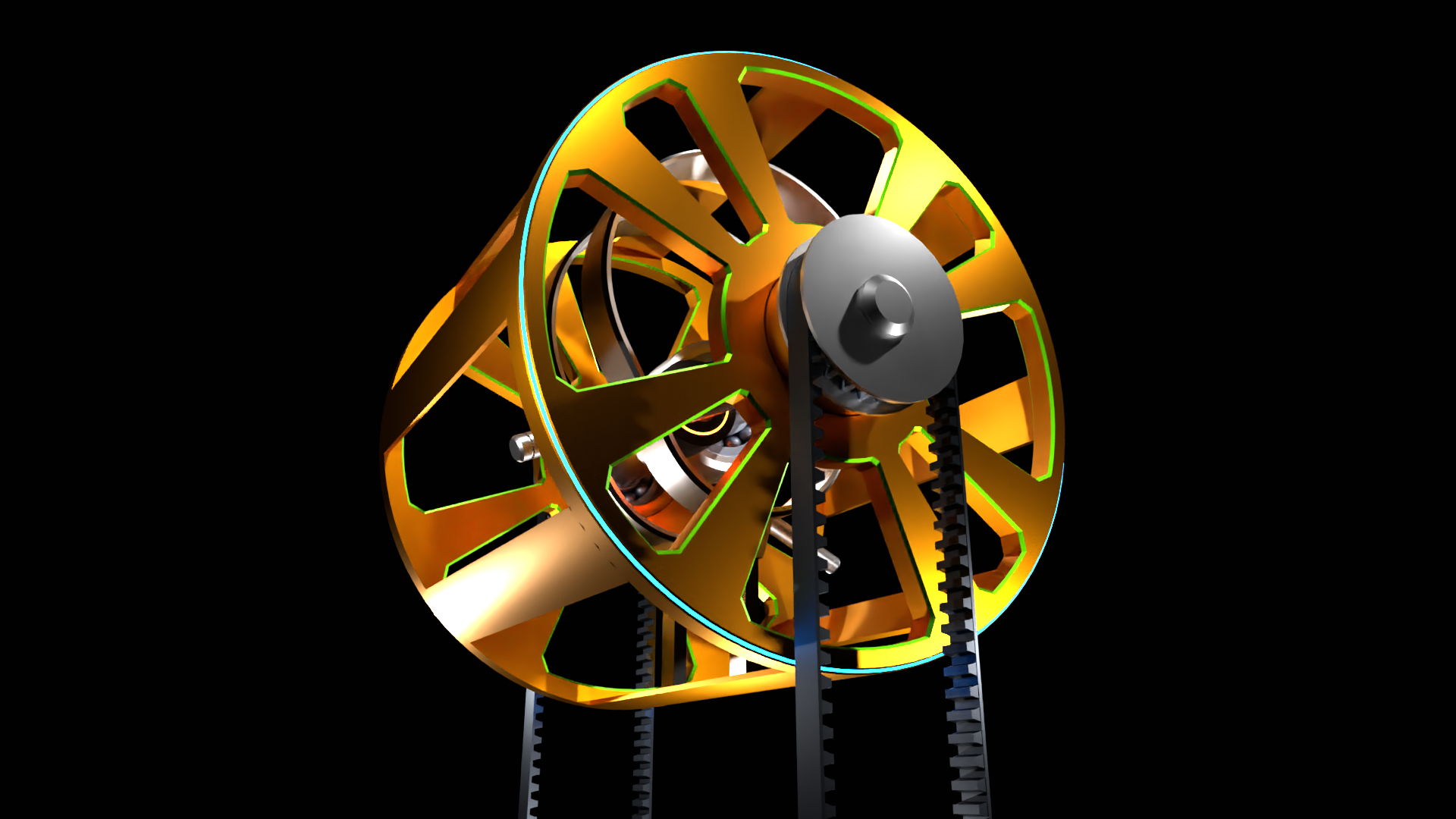
The shape of slightly other proposition of the same propulsion method however with gyroscopic stabilisation system of two rotating fast rings. Inside there are the same propulsion as on above pictures.
5 May 2021
Lately I was thinking about double sling effect inertial centrifugal and inertial force generator. It will consist of two contrary rotating masses, those masses will be guided by a linear bearings with welded short rods with double ball bearings. The masses will be moving along guided rods. The entire system will be rotate on egg shape external rims to obtain maximum force difference between two up and down position. The masses will be synchronized and in each loop will be passing by each other two times one time on the bottom and one time on the upper position. This system is not entirely balanced and to full balance there will be needed three such a generators placed on the corners of equilateral triangle. The system is not equipped in counterweights and the masses will be give away their full centrifugal force on the external rims. The centrifugal force is maximal in upper position in the while that both masses will be passed by each other and minimal in bottom position. This system is not entirely finished this is only the scheme of the aim system, which will be developed in further time.In the attached drawing the system is in lower position where the force is minimal. To solving is the question of delivering the external mechanical energy from the electric motor. I added the ball bearings on the separate shafts because they will be rotate in opposite direction. There was no way to balance the system by placed the generators in coplanar plane, so they are placed one by one. There was an opportunity to place them side by side but I decided to place them in this way to obtain more closed system for the reason of delivering the power from electric motor, but this question as is seen is still to solve. The side parts of rims are very close the main shafts so the masses hardly can pass between the rims and the main shafts, the enough distance is about several millimetres.
5 May 2021
I have made some preparations for axial inertial propulsion with rotating masses around central axis. The main motor centrally located type 775 24V DC brush motor.

.png)
.jpg)