20 August 2021
Accelerating a ferromagnetic sphere through a magnetic field and a variable stator radius. Magnetic starter with movable stator covers. If it were possible to induce the sphere to vibrate at extremely high frequencies in the range of hundreds, thousands of GHz, it might be possible to make the sphere heavier due to relativistic mass increase. However, this solution would be extremely difficult, and in reality, there are no proven solutions in this field except for the LHC (this applies to small elementary particles like protons), and practically every technology in this regard will be pioneering.
20 August 2021
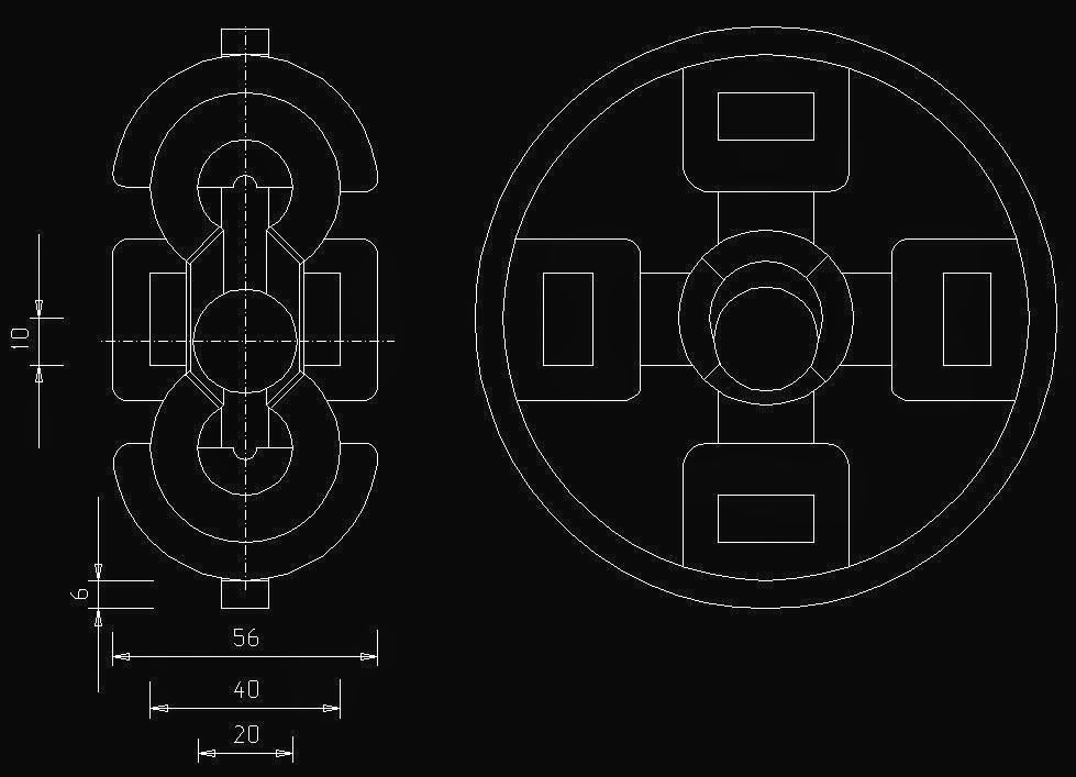
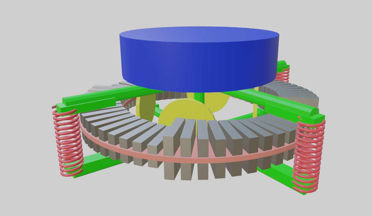
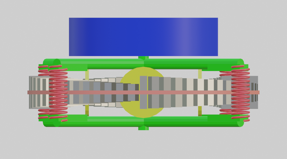
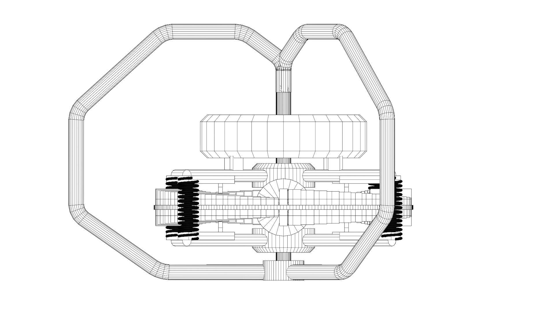
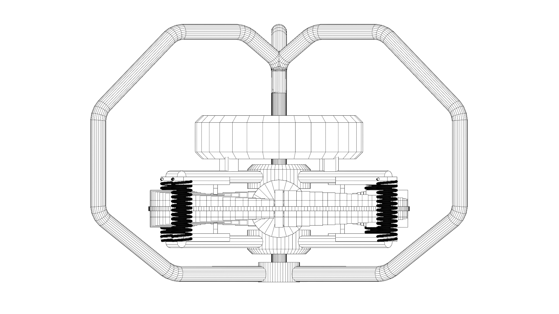
Interesting device, or rather just an ideogram of a device whose principle is based on magnetic repulsion between a rotor with magnets (here 4 pcs.) and a ring stator at the bottom of the device. When the rotor magnets approach the jump, they encounter a jump wheel that lifts them and allows them to move to the next cycle. The device works on the principle of repelling magnets - the rotor will be repelled in the direction of greater separation of the stator magnets from the rotor magnets in the horizontal and vertical plane, it is designed so that the distances are not constant but increase in one direction, i.e., in the direction of rotor rotation. The device can also be double-sided with compression springs, acting on tension (double rotor from below and above). The magnets are appropriately spaced every 3.125 mm in four independent rows. The device has not been tested, so it may not work as intended or may work partially.
20 August 2021
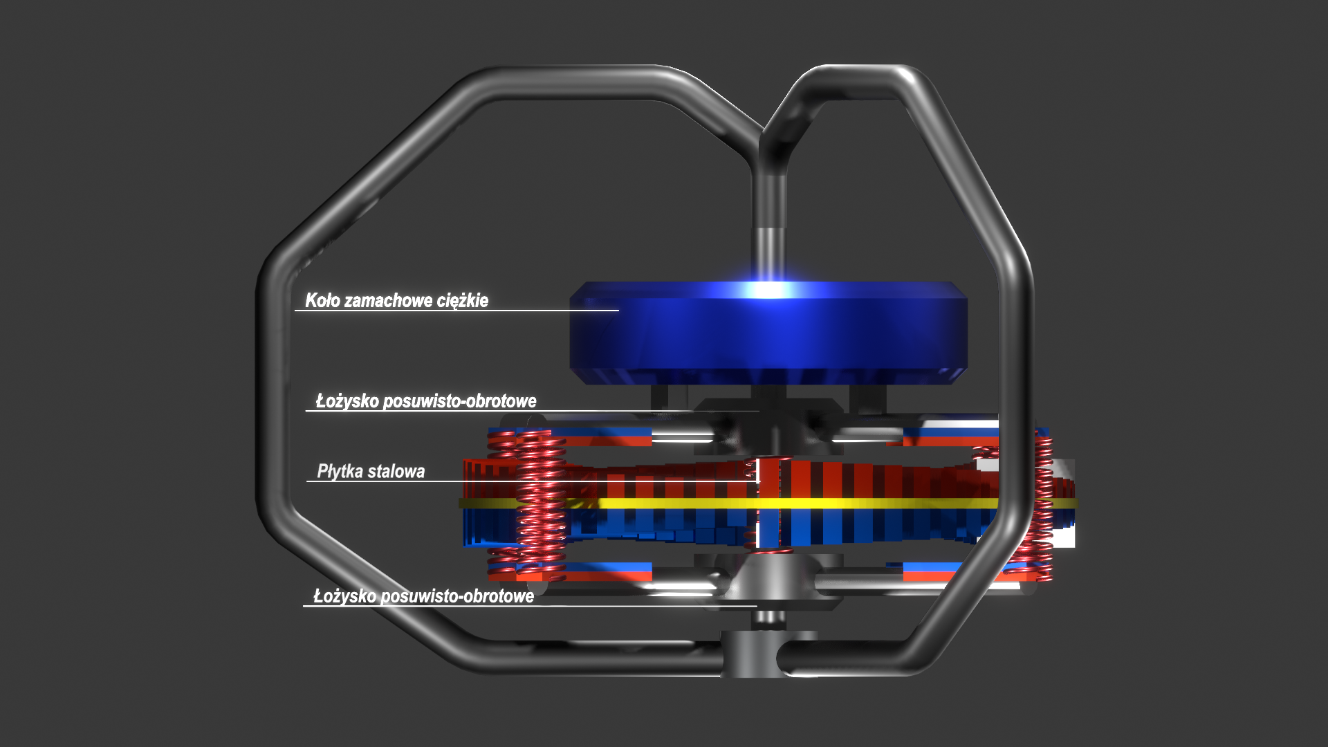
I came up with the idea of a device entirely based on magnetic and inertial forces, magnetic repulsion, the rotor is repelled in the direction of the magnets moving away from each other (in the direction of weaker magnetic interaction). The device generates torque, which can be transferred to a generator, thus obtaining free electrical energy. I used bar magnets, arranged in a row from the highest to the lowest. The main problem would be overcoming the jumps, where the highest magnets come into contact with the lowest, in the attached images I used elements to increase the distance, but there would be a loss due to friction, which would slow down the device. Recently, I came up with the idea of using steel plates that limit the spread of the magnetic field, placed on the vertical peaks of the connections on each side of the disc with magnets. In this device, the number of jumps is four. The device converts magnetic repulsion energy into cyclic rotation. The rotor is mounted on roller bearings, the stator is placed more in the center. Additionally, I used springs that increase the pressure on the stator elements of the rotor's magnetic covers. The strongest permanent magnets should be used, namely neodymium magnets. The device is based on the tendency of magnets to occupy the lowest energy position relative to each other. When a magnet interacts with another magnet for repulsion, it tries to deflect magnetically in one direction or the other, however, when another similarly polarized magnet is behind it, it will move to the position farthest from the arrangement of these magnets in the direction where there is no magnetic field or it is weaker. This is the principle of the device. Additionally, to increase the smoothness of operation, I used a heavy flywheel attached to the rotor from above. The rotor arms can be hinged to allow pressure by springs, I also considered using sliding-rotary bearings on which the rotor would be mounted. The rotor magnets should be as large as the device construction allows. The device should be constructed on an appropriate scale, depending on the type and size of the generator used.