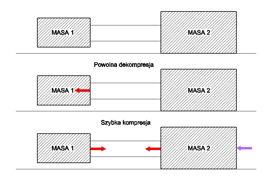
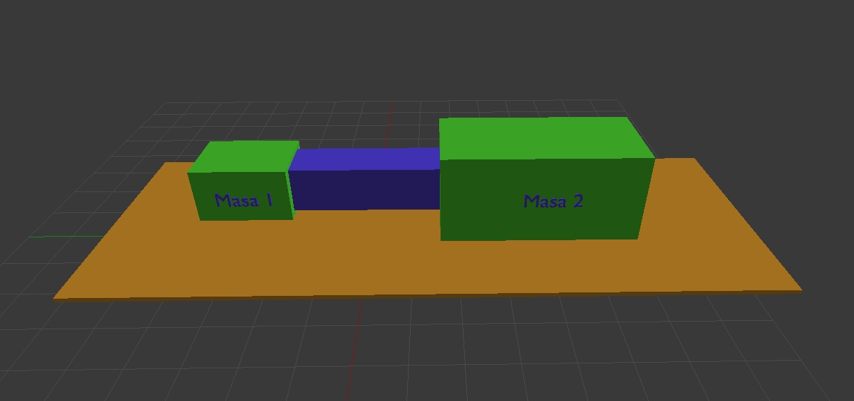
A propulsion system operating on the shock principle. Here, we have a situation in which mass 1 slowly shifts relative to mass 2. The connector experiences a change in geometry along its length. This connector can experience a change in geometry in several possible situations, for example, due to the piezoelectric effect, magnetostriction, or thermal expansion. Because this occurs at a low speed, the inertia of mass 2, which is greater than that of mass 1, prevents mass 2 from shifting and, consequently, from retracting the system. Then, contraction occurs, the connector between the masses experiences a sudden contraction and jerk. Now, mass 1 has the dynamic force to move the entire system because the contraction shortens the total length of the system. Then, the decompression phase occurs, but this time in a new position for the entire system. The steps of slow decompression and jerk repeat, and the cycle closes, allowing the system to move in space.
9 September 2020
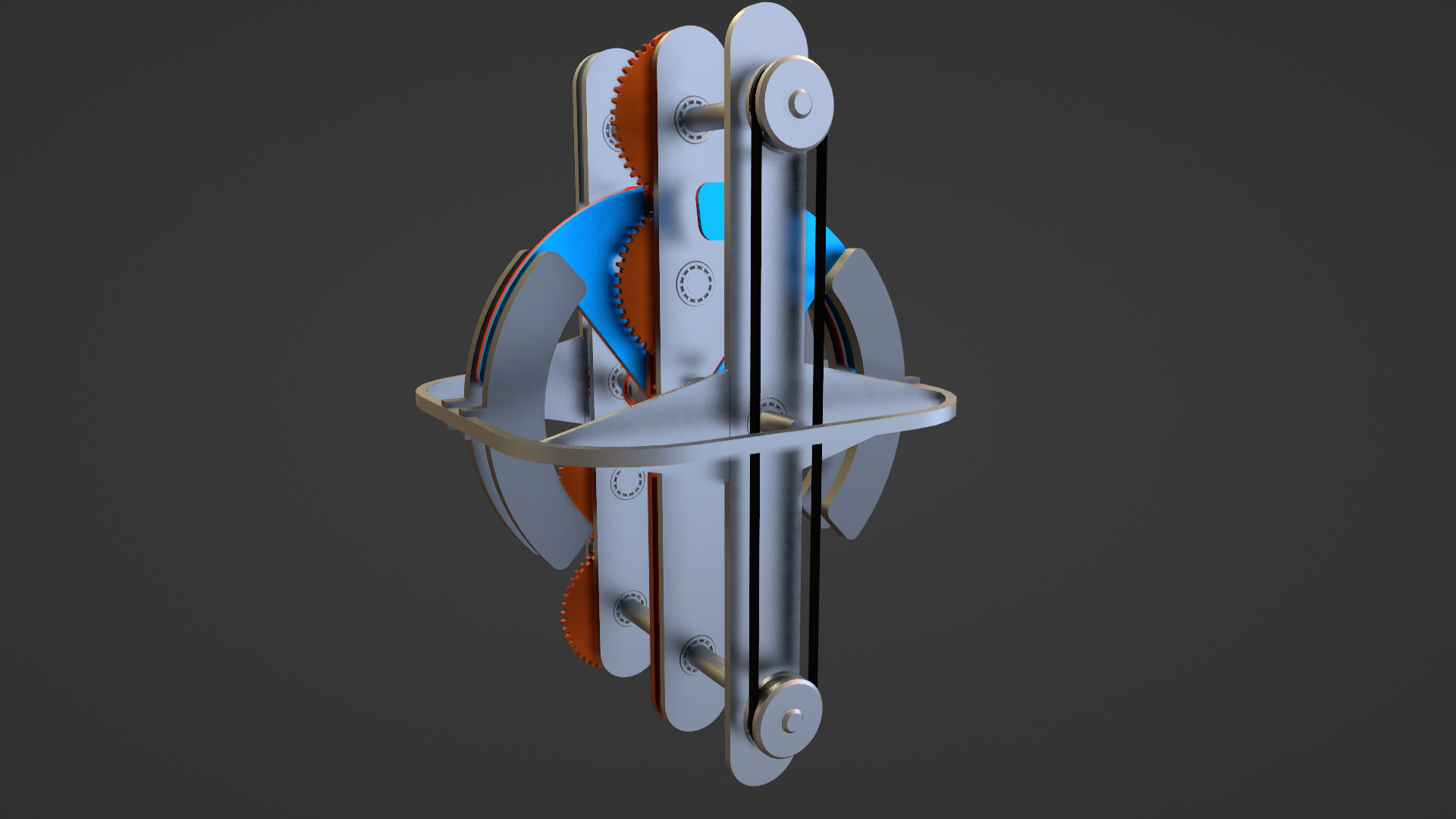
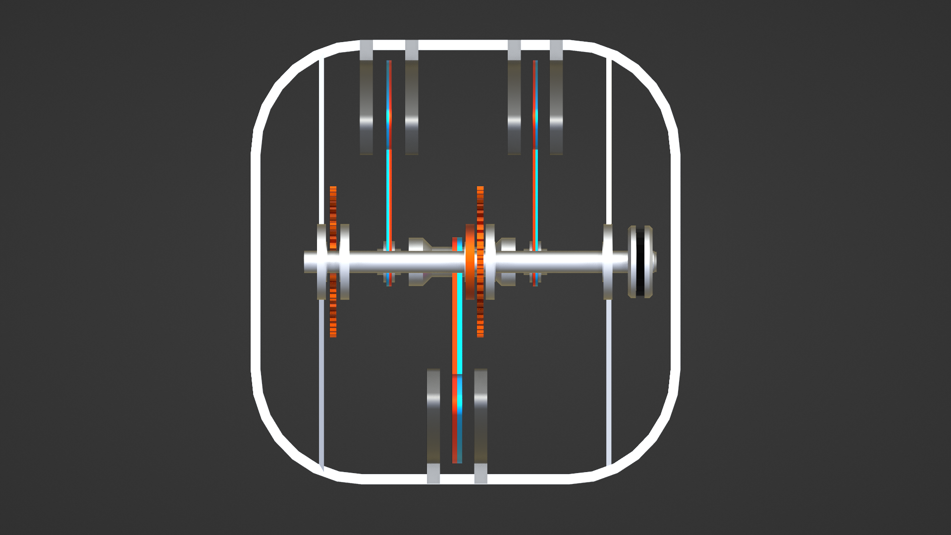
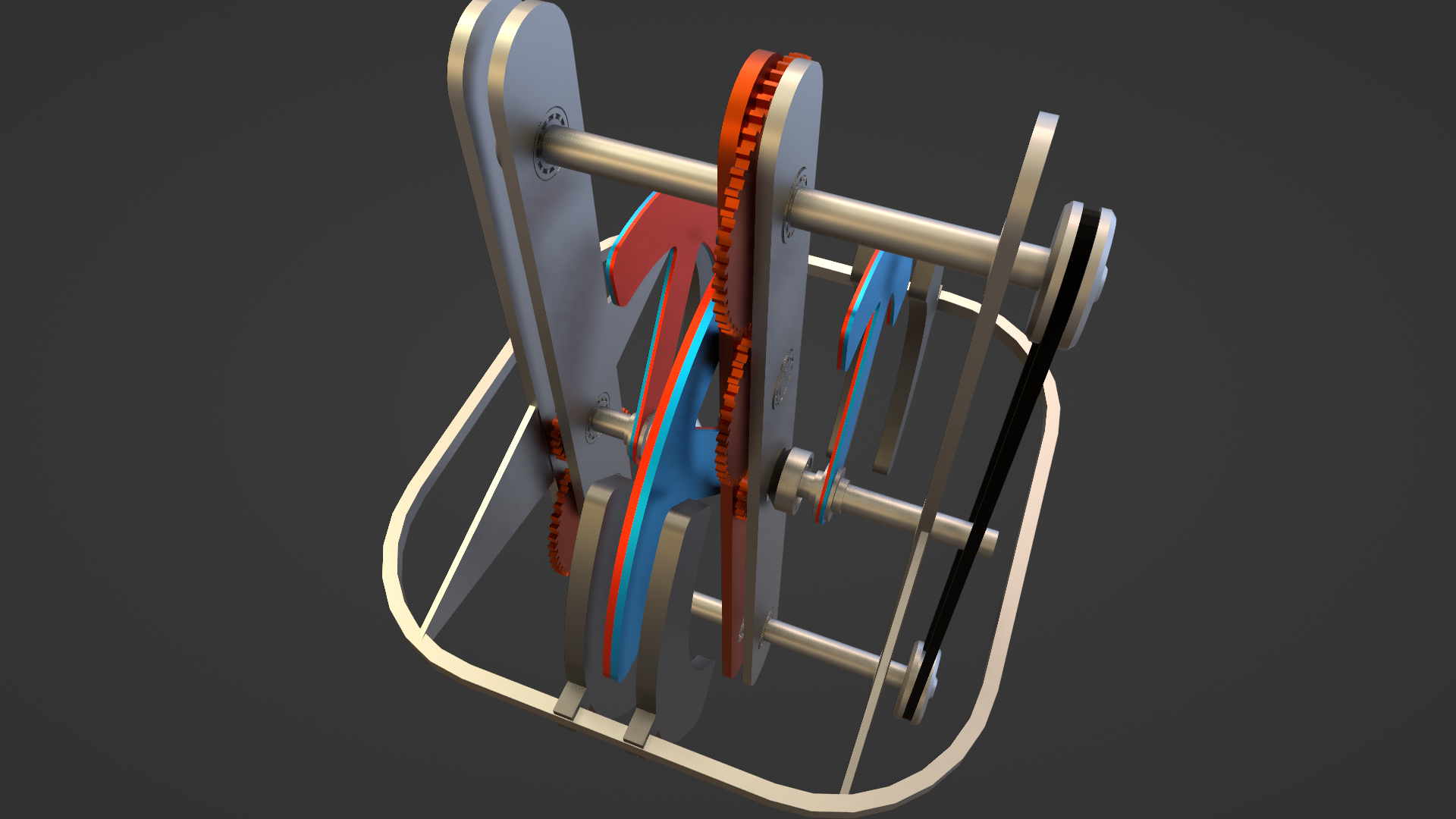
A side balanced directional ex-center device with permanent rotating magnets to generate one directional upward force and the second force downwardly which is, thanks magnets and steel bars, smaller. The problem of delivering mechanical force from electric motor is not solved here. Also, the problem of making counter rotational movement of magnets is not solved. The device is using attraction between steel and permanent magnets. When the magnets are passing between the steel plates, they are decelerated by the magnetic attraction between the interaction between those both parts. When they are leaving external steel plates approaching to upper position the steel plates which are bounded with the stator by additional external casing will tends to follow them, so the entire system will want to move upwardly and a little to inside of the device. The distances between the steel plates and rotating permanent magnets are not random, they are closer to the magnets and farther in each singular magnet system to avoid summing the opposite directional lift what would to result as a zero-result force coming from the entire system. The axe-like rotating permanent magnets are shown here in slightly schematic way, because they for practical use they won't be entirely magnetized only heads will be magnetized and they should be a little thicker. The two external magnets are of the same weight as this one in the middle, which is twice as thick as external single ones. The point is to obtain better balanced systemThe problem of delivering power from the electric motor is open here and may be important obstacle to obtain the success in this case. I was trying to add a tube on central shaft which ment to be placed on ball bearings on both sides, but I did not know how make the system counterrotating. The tube with the central magnet was ment to be rotating in one direction and the shaft with the external two magnets in opposite direction but delivering energy from the external electric motor to those both counterrotating systems encountered on a real trouble. I was trying to add a couple of gears but the need of delivering the power from external motor is colliding with my conception of locating the gears.As it is visible, I have added several changes. I solve the problem of delivering external power from the electric motor adding some gear boxes and transmission belt connection. Gears should be made from non-ferromagnetic material because they are near rotating magnets. I have added external holding rim for the steel plates. But it turns out that the V-belt should be eight however I have thought previously that opposite location of two of gear boxes will do, but it won't what is resulting from my observation of moving gears. This is slightly more developed system to, as I think, generation linear thrust upwardly. The magnets which are rotating will be in assumption pulling magnetically the entire device (using ferromagnetic plates on both sides of these magnets) The system should be balanced on both sides so the plates on both sides should have the same mass and mass of rotating magnetic blades should be the same - the two on one side should have the same mass as the one on the opposite side. The system for now has not solved entirely the problem of counter rotation due to the v-belt should be eight right now, and it can't be eight in this solution also applying the chain in eight is not satisfactory solution so I must find some other solution where this problem will be overcome.
9 September 2020
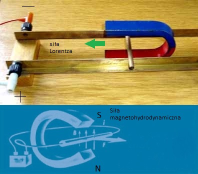
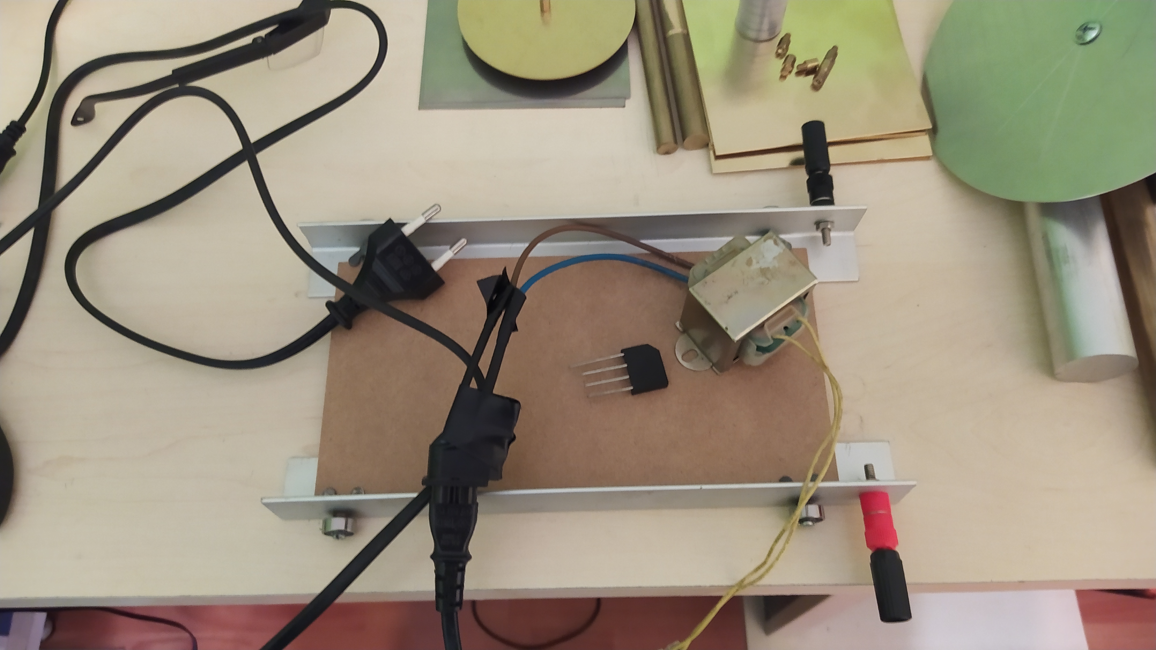
Chassis on which I intend to test the Lorentz force vector and whether this force is independent, meaning its occurrence will cause the chassis to move on bearings upon encountering an obstacle, or not. The weight of the chassis plus the weight of the magnets plus the weight of the moving rod is quite significant to move, and it is necessary to distinguish forces originating from inertia from magnetic forces, specifically the electromotive force itself. The entire system will be powered from a transformer through a bridge rectifier along with a bulb indicating current flow and circuit closure. Instead of a horseshoe magnet, I will use neodymium magnets so that the direction of the magnetic field forces acts on the vertical axis. Between these magnets, a metal rod will be loosely placed, and directly in front of it, the mentioned obstacle, and the theoretical problem will be to determine whether the current flowing through the rod will cause the cart to move forward, due to the obstacle being firmly connected to the rest of the chassis, the magnets being static and moving on this chassis. This theoretical problem and its solution will allow us to determine whether the electromotive force, and consequently the Lorentz force, can be an independent force, with no equal and opposite reaction.